You can learn brushless motor wiring by following easy steps. You also need to get ready with the right tools. Here is a table showing electric motor market share for 2025:
Motor Typ | Market Share (2025 Projection) | Usage Contexts and Notes |
|---|---|---|
Bürstenlose Motoren | ~40.1% | This type is growing fast. People like it for robotics, EVs, drones, and electronics. It works well and lasts a long time. |
Brushed Motors | Remaining ~59.9% | These are still used in old systems. They are also used when things need to be cheap or simple. |

Wiring a brushless motor the right way keeps it safe. It also helps the motor work its best. If you wire it wrong, the motor can get too hot. It might stutter or even stop working.
Get all your parts and tools before you begin. This guide will help you with three-phase wires and Hall sensor connections.
If you wire it wrong, these things can happen:
The motor may stutter or jerk.
You might see error codes or it may not start.
The motor can get too hot and break.
Wichtigste Erkenntnisse
Always connect the three-phase wires and Hall sensor wires the right way. This helps the motor run smoothly and stops damage.
Pick the correct motor, ESC, and battery by checking voltage and current. Make sure they work well together to keep your system safe and working well.
Use the right tools and wire sizes to make strong and safe connections. This helps stop overheating or short circuits.
Follow each wiring step carefully and check for safety before turning on your motor system.
Test your wiring setup well and fix problems early. This helps your motor last longer and work better.
Brushless Motor Wiring Basics
When you start with brushless motor wiring, you work with two main parts: the three-phase wires and the Hall sensor wires. These parts help your brushless dc motor run smoothly and efficiently. You will often see a wiring diagram or a diagram in manuals to show how these wires connect.
Three-Phase Wires
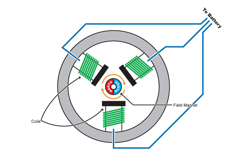
A brushless motor uses three wires for its main power connections. Each wire connects to a different set of coils inside the motor. The electronic speed controller (ESC) sends power through these wires in a special sequence. This sequence creates a rotating magnetic field that turns the rotor. You do not need brushes or a commutator like in older motors. The three-phase wires replace the mechanical switching found in brushed motors. If you look at a wiring diagram, you will see these three wires labeled as phases A, B, and C.
Tip: Always match the three-phase wires from the ESC to the motor. If the motor spins in the wrong direction, swap any two wires to reverse it.
Hall Sensor Wires
Hall sensor wires play a key role in brushless motor wiring. These wires carry signals from sensors inside the motor. The sensors detect the position of the rotor. The ESC uses this information to know when to switch the current in the three-phase wires. This process helps the motor start smoothly and keeps it running at the right speed.
Hall sensor wires must connect in the correct order for the motor to work well.
Some controllers can learn the correct order by themselves, but others need you to follow the wiring diagram closely.
If you connect the Hall sensor wires wrong, the motor may not start or may run poorly.
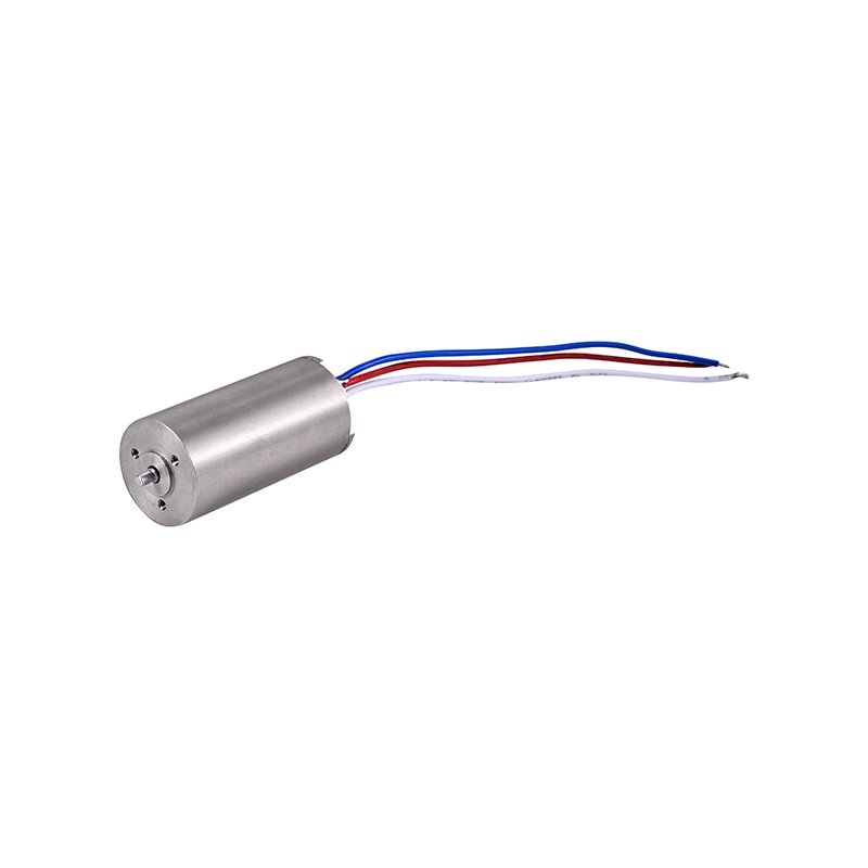
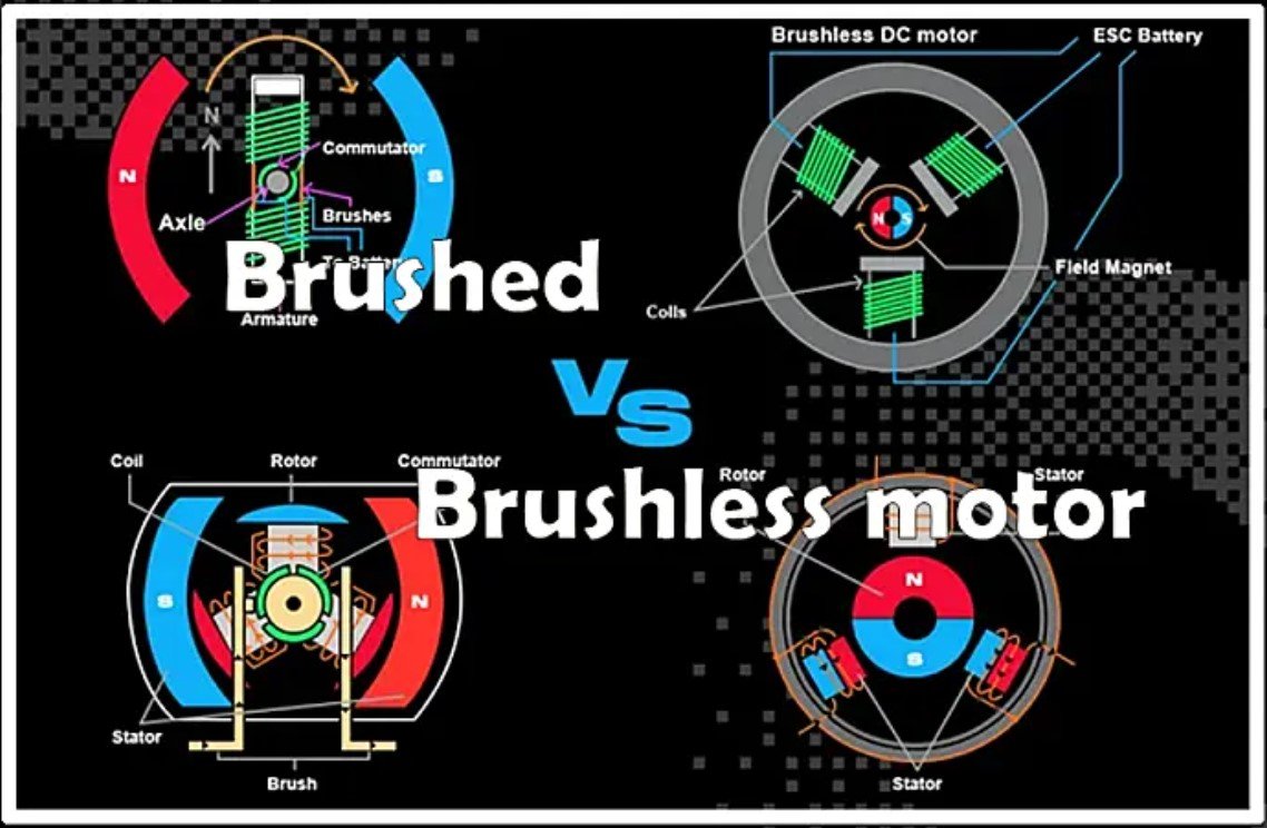
A brushed motor has a much simpler wiring setup. It uses brushes and a commutator to switch current. The wires connect directly to the brushes, which touch the spinning part of the motor. In a brushless motor, you do not have any wires going to the rotor. All the switching happens electronically, which means less wear and longer life.
Parts and Tools

Components List
Before you start, gather all the main parts you need. Each part helps your project work safely and well. The table below shows the most important parts and what they do:
Component / Aspect | Details / Specifications |
|---|---|
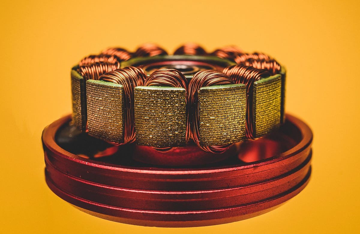
Stator with wire windings, Rotor with permanent magnets, Electronic Speed Controller (ESC), Position sensors (Hall effect), Control electronics | |
Wiring Phases | Three-phase wiring: Phase A (U) – Red or Yellow, Phase B (V) – White or Green, Phase C (W) – Black or Blue |
Wire Gauge Recommendations | Up to 10A: 18 AWG, 10-15A: 16 AWG, 15-20A: 14 AWG, 20-30A: 12 AWG, 30-40A: 10 AWG |
ESC Selection Criteria | Current rating, Voltage rating, Programming capabilities, Sensor support, Protection features |
Control Protocols | PWM, UART, I²C, CAN bus, Field Oriented Control (FOC) |
Safety Measures | Proper insulation, Adequate wire sizing, Strain relief, Protection circuits, Environmental considerations |
You also need a battery to power the ESC and motor. Most small brushless motors use a battery with about 10V. Make sure your battery can give enough current for your motor. For example, a brushless motor might use up to 13A for short times. The battery should give enough power without getting too hot.
Tip: Always check the battery’s max output and make sure it matches your ESC and motor.
Tools Needed
You need the right tools to make safe, strong connections. Here is a list to help you get ready:
Wire cutters and strippers to prepare wires
Soldering iron and solder to join wires
Heat shrink tubing or electrical tape for insulation
Multimeter to check voltage and if wires connect
Screwdrivers to mount parts
Zip ties or cable organizers to keep wires tidy
Safety glasses to protect your eyes
Battery charger for your battery
Always use the right wire size for your setup. Wires that are too thin can get hot if the battery gives a lot of current. Good insulation and neat wires help stop short circuits and keep things safe. When you connect the battery, check all wires before turning on the power.
Note: Never connect or disconnect the battery while the ESC is on. This can break your electronics.
Choosing Brushless Motor Components
Motor, ESC, and Battery
You need to pick the right motor, esc, and battery for your brushless setup. Start by checking the voltage range for your motor. Your battery must match this range to get the best speed and power. Many hobbyists use a li-po battery because it gives high current and light weight. Always make sure your esc can handle more current than your motor will draw. This keeps your system safe and helps prevent overheating.
When you choose an esc, look at its voltage and current ratings. The esc must match your battery voltage and provide enough current for your motor. Some esc units have extra features like waterproofing or sensor support. These features help if you use your setup in wet or rough places. You also need to check the connectors on your battery and esc. Common types include XT60, XT90, EC5, and Deans T. Use quality adapters if you need to connect different plugs.
Tip: Always follow the correct connection steps. Double-check polarity before you connect your battery to the esc.
Compatibility Tips
You can avoid most problems by checking compatibility before you buy parts. Here are the most common issues and how to prevent them:
Match the voltage ratings for your motor, esc, and battery. Using the wrong voltage can damage your parts.
Make sure your esc can handle the highest current your motor will use.
Pick a motor with enough torque for your project. If the motor is too small, it may stall or overheat.
Choose the right speed (RPM) for your needs. Some motors spin too fast or too slow for certain jobs.
Check that your esc and motor use the same control method, like trapezoidal or field-oriented control.
Use the correct wiring and keep cables short to avoid signal loss or interference.
Make sure your battery can supply enough current. Multiply the C-rating by the capacity (Ah) to find the max current.
You should also check the physical fit. Look at the motor mount, shaft size, and propeller adapter. Good cooling helps your esc and motor last longer. Always follow calibration steps for your electronic speed control to keep your system running smoothly.
Brushless Motor Wiring Steps
Wiring your brushless motor system takes careful attention. You need to follow each step to make sure your setup works safely and smoothly. This section will guide you through every connection, from the motor to the ESC, then to the power source, and finally the Hall sensors. You will also learn how to check your work before powering up.
Connect Motor to ESC
Start by connecting the three main wires from your brushless motor to the ESC. These wires are often labeled A, B, and C, or they may use colors like yellow, blue, and green. The ESC will have three matching output wires. You can connect these wires in any order for your first test. If the motor spins in the wrong direction, simply swap any two of the three wires. This will reverse the rotation. This method works because the ESC sends power in a sequence, and swapping wires changes the phase order.
Tip: Use bullet connectors for easy swapping and secure connections. Make sure the connectors fit tightly to avoid loose contacts.
Check that the wires are not frayed or pinched. Loose or damaged wires can cause poor performance or even short circuits. If you use soldered connections, inspect each joint for a shiny, solid finish. Cold solder joints can lead to intermittent problems.
Connect ESC to Power
Next, connect the ESC to your battery or power supply. The ESC has two thick wires for power: red for positive (+) and black for negative (–). Always match red to red and black to black. Double-check the polarity before connecting. Reversing the battery leads can damage the ESC and cause a short circuit.
Use the correct wire gauge for your setup. Wires that are too thin can overheat. Keep the battery leads as short as possible—no longer than 18 inches—to reduce voltage drops. High-quality connectors like XT60 or EC5 help handle the current safely.
The ESC also has a signal wire, usually yellow or white, which connects to your controller (like an Arduino or RC receiver). The black or brown wire is ground. Only connect the red wire in the signal cable if your controller needs power from the ESC. If your controller is already powered, leave the red wire disconnected to avoid damage.
Note: Do not attach the propeller or load during your first test. This keeps you safe if the motor starts unexpectedly.
Connect Hall Sensors
If your brushless motor uses Hall sensors, you need to connect these wires to the ESC or motor controller. Hall sensors help the ESC know the rotor’s position, which allows for smooth starts and better control.
Most Hall sensor cables have five wires:
Red: 5V power supply
Black: Ground
Yellow, Blue, Green (or similar): Sensor signals (often labeled HU, HV, HW)
Connect the red wire to the 5V output on the controller, and the black wire to ground. Match the signal wires to the correct inputs on the ESC. Sometimes, the colors do not match exactly, so check your wiring diagram or manual. If the motor does not start or runs rough, try swapping two of the signal wires. Testing different combinations helps you find the best match for smooth operation.
Some setups include a sixth wire, often white, for extra features like temperature sensing. Only connect this if your controller supports it.
Tip: Always test the Hall sensor connections before running the motor at full power. Incorrect wiring can cause the motor to stall or overheat.
Safety Checks
Before you power up your system, run through these safety checks:
Inspect all wires for damage, loose connectors, or poor solder joints.
Make sure the motor shaft spins freely by hand. Listen for grinding or scraping sounds.
Check that the installation area is dry and well-ventilated.
Confirm that the battery voltage and current match the ESC and motor ratings.
Separate all wires and spin the motor by hand to check for shorts. If you feel resistance, stop and inspect the wiring.
Secure all connections with heat shrink tubing or electrical tape.
Keep the ESC and motor cool. Add a fan or heatsink if needed.
Disconnect power before making any changes to the wiring.
⚠️ Common mistakes include reversed battery polarity, using wires that are too thin, poor soldering, and loose connectors. These can cause overheating, short circuits, or even permanent damage to your ESC or motor.
If you follow these steps, you will have a safe and reliable brushless motor wiring setup. You now know how to control brushless motor systems with confidence.
Troubleshooting and Checklist
Common Issues
You might have problems when wiring a brushless motor. First, check every wire connection. Look for broken or frayed wires. These can make the motor stop working. Check the bearings for damage or wear. Bad bearings can make the motor shake or sound loud. Look at the rotor and stator for cracks or rust. Use a multimeter to test the windings, control boards, and esc for resistance and if they connect.
Manufacturers say to follow these steps to fix wiring problems:
Make sure your power supply matches the motor’s voltage and current. Use a multimeter to check this.
Look at each wire connection for loose spots, damage, or rust. Tighten or change them if needed.
Compare your wiring to the motor’s diagram so you do not make mistakes.
Test the esc for problems. Watch for error codes or strange signals. Update the firmware or try another esc if you need to.
Check Hall sensors by turning the motor with your hand. Use an oscilloscope to see if the signals look good.
Look at signal cables for damage or noise. Use shielded cables if you need them.
Here is a table that shows common reasons for wiring failure and how to stop them:
Cause | Prevention Tip |
|---|---|
Overloaded windings | Use correct voltage and overcurrent protection |
Degraded insulation | Inspect and replace insulation regularly |
Improper installation | Align and mount motor correctly |
Loose windings | Tighten windings and reduce vibration |
Debris and contamination | Keep motor clean and maintain cooling |
Testing the Setup
After you finish wiring, you need to test your setup. Follow these steps:
Spin the motor by hand with wires apart. If you feel it is hard to turn, check for shorts.
Use a drill to spin the motor with no power. Listen for strange sounds or heat.
Label the three motor wires. Measure AC voltage between each pair while spinning. If the voltages are not the same, you have wiring problems.
Use a meter to check for shorts between the stator and windings.
Measure the no-load current. Compare it to the numbers from the manufacturer.
Turn off the power and use a multimeter in ohm mode. Measure resistance between each pair of wires. The readings should be 0.3–0.8 ohms.
Check insulation with a megohmmeter. If the reading is less than 600 megohms, the cable is damaged.
Measure amperage in the circuit. If the numbers jump around, there are big problems.
A good test shows resistance within 5% of what you expect, balanced inductance, and insulation resistance above 100 M-Ohms. If all tests are good, your esc and motor are ready to use.
Brushless Spindle Motor Tips
When you use a brushless spindle motor, always follow the maker’s instructions. Good wiring and setup help your motor last over 20,000 hours. Do not overload the esc or motor. Keep the motor clean and check for dirt often. Use the right esc settings for your spindle motor. Check wires and connectors often for damage. If you hear noise or feel shaking, stop and check the bearings and alignment. Good care and careful wiring help your spindle motor work well for many years.
You now know the main steps to wire a brushless motor. Always check your wires before turning on the power. Here is a checklist to help you:
Make sure the phase and sensor symbols match the diagram.
Check that sensor wires go to the right places on the ESC.
Use a multimeter to test every connection.
During a low-power test, listen for strange noises.
You can read more guides about advanced motor controllers and PCB design to learn more. Careful wiring keeps you safe, helps your system stay cool, and makes your motor last longer.
FAQ
What should you do if your brushless motor spins the wrong way?
Swap any two of the three phase wires between the motor and ESC. This will reverse the direction. You do not need to change anything else.
Can you run a brushless motor without Hall sensors?
Yes, you can run many brushless motors without Hall sensors. The ESC will use sensorless mode. You may notice rough starts or less control at low speeds.
How do you know if your ESC is compatible with your motor?
Check the voltage and current ratings on both the ESC and motor. Make sure the ESC supports the type of motor you have. Always read the manuals for both parts.
Why does your motor get hot during use?
Your motor may get hot if you use thin wires, have poor connections, or overload the motor. Check all wiring and make sure you use the right size wires.
What is the safest way to test your wiring before full power?
Always test your setup without a propeller or load. Use a low voltage first. Listen for strange sounds and watch for heat. If you see or hear anything odd, stop and check your wiring.