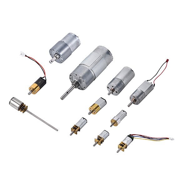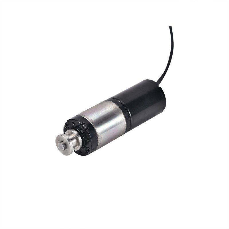
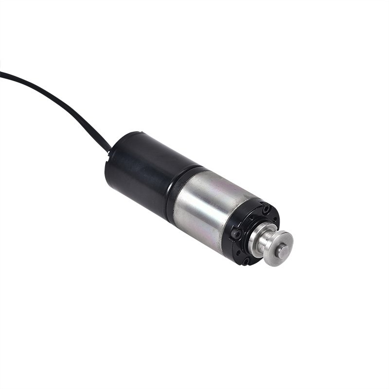

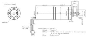
Customizable items: 1. Length and shape of the shaft; 2. Voltage, output speed, torque, etc. ; 3. Adding connectors, lead wires; 4. Adding gears to shaft; 5. Adding encoder.
| Ratio | MPN | Voltage | No Load | On Load | Stall | ||||||||||
| Operating Range (V) | Rated Voltage(V) | Current (mA) | Speed (rpm) | Current (mA) | Speed (rpm) | Torque (g.cm) | Current (A) | Torque (g.cm) | |||||||
| 4 | IND-36GMB3650-4 | 22.0-26.0 | 24 | 200 | 1600 | 1000 | 1300 | 500 | 2 | 2000 | |||||
| 100 | IND-36GMB3650-100 | 22.0-26.0 | 24 | 160 | 65 | 600 | 120 | 500 | 2 | 6000 | |||||
Gearbox sheet
| Gear box length/L(mm) | Number of stage | Gear Ratios | ||||||||||
| 26.5 | 1 | 1/4 | – | – | – | – | ||||||
| 38.5 | 2 | 1/19 | – | – | – | – | ||||||
| 48.5 | 3 | 1/51 | 1/100 | 1/139 | – | |||||||
| 55.5 | 4 | 1/189 | 1/264 | 1/369 | 1/516 | 1/720 | ||||||
*Note: Inter-rotor BLDC motor, sensor
Gear ratio selection is straightforward in principle:
Ratio moves you toward the target output RPM
It also changes torque margin and efficiency (and can affect noise/backlash)
If you send the basics below, we’ll propose a ratio/stage combination and confirm a working point:
target output RPM under load
continuous torque & peak torque
duty cycle (run time, starts/hour, any end‑stops or jams)
ambient temperature and any airflow/heat sinking assumptions
shaft/mounting drawing (recommended)
Most delays happen because the mechanical interface is decided late. If you already know them, share:
For integration and validation work, we can provide:
Start from the output requirement: RPM under load and torque (continuous/peak). If you share those two numbers plus the duty cycle, we can recommend the ratio/stage option and check current/thermal margin.
Output RPM under load, continuous/peak torque, duty cycle, end‑stop/stall events (if any), voltage range, and the mechanical interface drawing.
It depends on the working point and thermal path. Continuous duty is possible, but we need your load and ambient conditions to confirm temperature rise and expected life.
Voltage range, target output RPM (under load), continuous/peak torque, duty cycle, space limit (OD/length), and a shaft/mounting drawing if available.
Yes. Motor curve data and STEP/2D drawings are available on request for engineering review.
Yes—based on duty cycle and load profile, with assumptions stated so your team can use it in validation planning.