A planetary gearbox (often called an epicyclic gearbox) is one of the most compact ways to turn high motor speed into usable output torque. If you searched “how planetary gearbox works,” the short answer is: it splits load across multiple planet gears while keeping input and output on the same axis—so you can get high reduction in a compact package. But “planetary” is an overloaded label: the same basic architecture can be built for quiet consumer products, precision positioning, or high-duty industrial motion.
If you’re an OEM engineer selecting a planetary gear motor or a standalone planetary gearhead, the cost of a wrong assumption is usually paid later—thermal issues, noise, backlash complaints, unexpected wear, or a second round of prototypes.
This guide focuses on what matters in selection: how the mechanism actually transmits torque, what the major types are, and how to specify the parameters that prevent surprises.
What an epicyclic (planetary) gearbox is
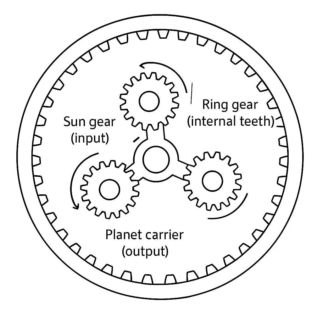
A planetary (epicyclic) gear train has four functional elements:
- Sun gear: the central gear, often the input.
- Planet gears: multiple gears that mesh with the sun and the ring.
- Ring gear (annulus): the outer gear with internal teeth.
- Carrier: the structure that holds the planet shafts and often becomes the output.
Because multiple planet gears share the load, a planetary stage can deliver high torque density in a coaxial form factor. That’s why planetary gear motors are common when you need torque in a tight envelope (medical devices, automation, security, compact robotics).
For a product-level overview of where planetary gear motors are typically used (and what configurations exist across diameters and voltages), see INEED’s planetary gear motors.
How planetary gearbox works
Most planetary gearboxes used for reduction in compact gear motors use a common configuration:
- Ring gear fixed (stationary)
- Sun gear driven (input)
- Carrier outputs (output)
Here’s the key intuition:
- The sun drives the planets.
- The planets “walk” around the inside of the fixed ring.
- The carrier follows that walking motion and becomes the reduced-speed, higher-torque output.
Pro Tip: When you’re debugging a speed/torque mismatch, first confirm which member is fixed in your gearbox. Same gearset, different fixed member → different ratio and even different rotation direction.
If you want a component-level explanation of power distribution and why the planetary layout is compact, see INEED’s guide to how a planetary gearbox works.
Planetary gear reduction ratio (and why stage count matters)
Engineers often search “planetary gear reduction ratio” because it’s where the mistakes start: people treat a planetary stage like a simple two-gear pair.
For the common reduction configuration (ring fixed, sun input, carrier output), the idealized ratio is:
- Reduction ratio: ( i = 1 + \frac{N_r}{N_s} )
Where:
- (N_r) = number of ring teeth
- (N_s) = number of sun teeth
A quick numeric example:
- If (N_s = 20) and (N_r = 60), then ( i = 1 + 60/20 = 4:1 )
- So 1000 rpm at the sun ideally gives ~250 rpm at the carrier (before losses)
Multi-stage planetary reduction
When you stack stages, the ratios multiply.
- Stage 1 ratio: (i_1)
- Stage 2 ratio: (i_2)
- Total ratio: (i_{total} = i_1 \times i_2)
This matters because:
- Higher ratio typically means more stages.
- More stages typically means more cumulative loss (efficiency) and more cumulative compliance (torsional wind-up), even if each stage is well made.
So the selection question isn’t “Can I get 100:1?” It’s “Can I get 100:1 within my thermal, noise, and positioning error budget?”
Planetary gearbox types (what the term actually covers)
Below is a practical taxonomy for OEM selection. The goal is not to be academically complete—it’s to help you choose what to spec and what to verify.
Comparison table: planetary gearbox types by stages / precision / efficiency / application fit
| Type (common in OEM motor assemblies) | Typical stages | Precision (typical backlash bands)* | Efficiency (selection-relevant view) | Where it fits best |
|---|---|---|---|---|
| Standard spur planetary (metal gears) | 1–3 | Medium (often ~10–15 arcmin class, application-dependent) | High per stage; drops with more stages | General automation, compact actuators, security devices, medium-duty positioning |
| Helical planetary | 1–3 | Medium to high (depends on build quality) | Similar or slightly lower than spur; often quieter under load | Noise-sensitive applications; smoother torque delivery |
| Low-backlash precision planetary | 1–3 | High (single-digit arcmin class; preloaded designs) | High, but watch heat at high ratio | Robotics joints, lab automation, dosing, precision stages |
| Plastic stage(s) planetary (noise-optimized) | 1–2 | Low to medium | Can be high at light loads; watch wear and temperature | Consumer/medical devices where acoustic noise is critical |
| High-ratio multi-stage planetary | 2–4 | Depends on quality; can be acceptable but cumulative | Overall efficiency reduces as stages stack; verify thermal rise | Very low output speed needs; compact winch/valve actuation |
| Stepped/compound planetary (advanced ratios in compact space) | 1–2 (complex) | Application-specific | Can achieve higher ratios per stage; design-sensitive | Specialized designs where envelope limits force ratio density |
*Backlash values vary widely by supplier and size. Use the table as a selection map, then verify on the specific gearbox family you’re qualifying.
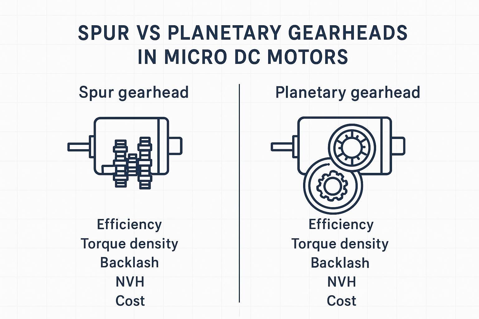
If you’re deciding between planetary and spur gear motors at a system level, INEED’s spur vs planetary gear motor comparison is a relevant internal link.
How to select a planetary gearbox: parameters that prevent redesigns
A good selection process starts with the application load profile—not the catalog ratio list.
1) Reduction ratio and output speed
Start from the output requirement:
- Required output speed: (\omega_{out})
- Expected motor speed under load: (\omega_{in})
- Target ratio: ( i \approx \omega_{in} / \omega_{out} )
If you want a quick refresher on how gear ratios trade speed for torque in gearmotor assemblies, INEED also covers the basics in Gearbox Motor: Basic Principles and Functionality Explained.
Quick sanity check: If your ratio goes up, output speed goes down and output torque goes up (ignoring losses). If your test results don’t follow that trend, re-check which member is fixed and whether you’re measuring motor speed under load.
Practical notes:
- If your ratio requires 3+ stages, assume you’ll need to manage heat and possibly accept more compliance/backlash than a 1–2 stage design.
- If the application reverses direction frequently, backlash and torsional stiffness will often dominate perceived performance.
2) Torque: continuous vs peak (and service factor)
For selection, separate at least two torque levels:
- Continuous / RMS torque (thermal driver)
- Peak torque (strength driver: acceleration, start/stop, impact)
A planetary gearbox can survive high peak torque only if:
- the peak is short
- the duty cycle allows cooling
- the output shaft loads don’t overload bearings
3) Efficiency and thermal budget
High reduction is not free:
- Each stage introduces loss.
- Loss becomes heat.
- Heat changes lubrication behavior, plastic gear strength, and motor winding temperature.
Selection approach:
- Use the ratio to estimate output torque and speed.
- Then check whether the combined motor + gearbox can dissipate the expected losses in your ambient environment.
⚠️ Warning: If your system already runs warm at a low ratio, increasing the planetary gear reduction ratio is likely to push you into thermal derating—even if the torque rating looks fine on paper.
4) Backlash, torsional stiffness, and what “precision” actually means
Backlash is what you feel as “deadband” when reversing direction. But in an OEM assembly, what you care about is often:
- Lost motion during reversals
- Repeatability under load
- Elastic twist under torque (compliance)
Guidelines:
- If you have frequent reversals or closed-loop positioning, treat backlash and stiffness as first-class selection parameters.
- If you only run one direction with constant load, backlash may matter less than noise, efficiency, and life.
5) Radial load, axial load, and overhung load
Many “mystery failures” are not gear tooth failures—they’re bearing load issues.
You need to know:
- Is the gearbox output driving a pulley, gear, or eccentric load?
- What is the overhung distance from the output bearing to the load line?
Even a well-sized torque rating won’t save a gearbox whose output bearing is overloaded by a belt tension or cantilevered load.
6) Noise and vibration (especially in small gear motors)
Noise is often driven by:
- gear mesh quality (tooth geometry, finish)
- alignment and carrier stiffness
- speed (noise rises fast with input rpm)
- material pairing (plastic vs metal)
If acoustic noise is a hard requirement, it should influence the gearbox type choice early (e.g., helical vs spur, or plastic stage(s) where load permits).
7) Environment, lubrication, and lifetime
Be explicit about:
- ambient temperature range
- contaminants (dust, cleaning fluids, moisture)
- expected life cycles and duty cycle
For high-duty applications, plan how you’ll validate lifetime and what you’ll monitor (temperature rise, noise, current draw, backlash growth).
A practical selection workflow (engineer-friendly)
Use this as a clean handoff checklist between system engineering and supplier engineering.
Worked example: turning requirements into a ratio + torque check
Assume you have a small actuator and you’ve measured/estimated:
- Motor speed under load: (\omega_{in}) ≈ 6,000 rpm
- Required output speed: (\omega_{out}) ≈ 300 rpm
- Continuous output torque requirement: (T_{out,cont}) ≈ 0.3 N·m
- Peak output torque during acceleration: (T_{out,peak}) ≈ 0.9 N·m
Step A — ratio estimate
( i \approx \omega_{in}/\omega_{out} = 6000/300 = 20:1 )
That’s typically a two-stage planetary (not always, but commonly), which is your first flag to check heat.
Step B — torque back-calc (sanity check)
A gearbox doesn’t create power; it trades speed for torque. Ignoring losses for a quick check:
- (T_{in} \approx T_{out}/i)
So for continuous torque:
- (T_{in,cont} \approx 0.3/20 = 0.015) N·m
For peak torque:
- (T_{in,peak} \approx 0.9/20 = 0.045) N·m
In the real world you’ll need to account for efficiency and duty cycle. The point of this step is not “final sizing”—it’s catching unit mistakes and unrealistic expectations before you order parts.
Step C — what to verify in EVT
- Does output speed land near 300 rpm under the expected load (not no-load)?
- Does temperature rise stabilize within your limit at the duty cycle?
- Is peak torque event short enough that you’re not heating the gearbox continuously?
- Do reversals cause unacceptable lost motion (backlash + compliance)?
Step 1 — Define the load profile
- Required output speed range
- Continuous torque (RMS) and peak torque
- Duty cycle (on/off, starts per minute)
- Direction changes and reversal frequency
Step 2 — Choose the ratio and stage strategy
- Start with the lowest ratio that meets output torque and speed
- Minimize stage count when efficiency/heat matter
- If high ratio is unavoidable, plan for thermal validation early
Step 3 — Lock the mechanical interface constraints
- Envelope and mounting constraints
- Output shaft type and length
- Any radial/axial load requirements
- Space for encoder/feedback (if needed)
Step 4 — Specify precision requirements in measurable terms
Instead of “high precision,” specify:
- backlash target (or allowable lost motion)
- repeatability requirement
- acceptable torsional twist under torque (if you have it)
Step 5 — Verification plan for EVT/DVT
Plan what you will measure before you cut metal:
- No-load and loaded speed vs current
- Temperature rise at worst-case duty
- Noise at defined speed/load points
- Backlash and lost motion after a burn-in period
If you need a reliability/derating lens specifically for planetary gear motors (what to watch, how to avoid early failures), see INEED’s planetary gear motor derating article.
Planetary gearbox vs planetary gear motor (when to think about the motor too)
A planetary gearbox is the reduction stage. A planetary gear motor is the integrated unit: motor + planetary gearbox.
The practical implication:
- If you’re buying a planetary gear motor, your thermal budget is shared between motor copper loss and gearbox loss.
- If you’re buying a gearbox to pair with a motor, you can sometimes improve results by changing motor speed, winding choice, or control strategy.
If you want a concise definition-oriented explanation of the integrated unit, use INEED’s “what is a planetary gear motor”.
Common questions OEM teams ask about planetary gearboxes
Does a planetary gearbox increase power?
No. A planetary gearbox (like any gearbox) redistributes the same input power into a different speed/torque combination. You get more output torque at lower output speed, but you also have losses (heat), so output power is always slightly lower than input power.
How many planetary stages do I need?
A good rule of thumb is:
- Choose the lowest ratio that meets your output requirement.
- Prefer fewer stages when thermal margin is tight.
- If your ratio pushes you into 3+ stages, plan to validate temperature rise early—don’t wait for the integrated prototype.
What’s the difference between planetary gearbox backlash and positioning error?
Backlash is the mechanical clearance you feel when reversing direction. Positioning error in a real system is backlash plus elastic twist (compliance), plus control loop behavior, plus any coupling/shaft flex. If your application reverses often, treat backlash and stiffness as measurable requirements—not marketing terms.
When should I choose a planetary gear motor instead of a separate motor + gearhead?
Choose an integrated planetary gear motor when you want a compact, validated package and you don’t need to optimize every component independently. Choose separate components when you need more control over motor winding, speed, encoder integration, thermal coupling, or mounting constraints.
Next steps: get a neutral spec review
If you’re selecting a planetary gearbox (or planetary gear motor) for a space-constrained OEM design, the fastest way to reduce iteration is to share a short spec pack:
- envelope and mounting constraints
- ratio target and output speed range
- continuous and peak torque + duty cycle
- radial/axial load assumptions
- noise and backlash targets