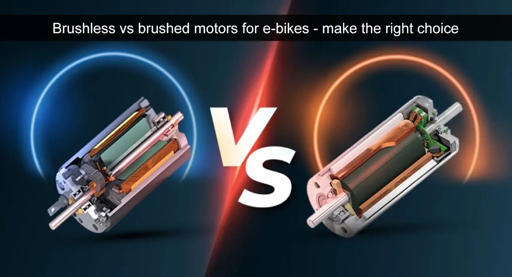
From our previous introduction, we learned that the control of brushless DC motors is different from that of brushed motors. Because brushless DC motors rely on electronic commutators rather than mechanical commutators. So how does the brushless motor achieve electronic commutation? Please continue reading this article – How to control a brushless DC motor?
Let me review the basic knowledge of brushless motors again.
What Is Brushless DC Motor?
Brushless DC motor is a kind of DC motor, there is no traditional brushless DC motor. It has two main advantages over brushed DC motors:
Extended service life and reduced maintenance frequency: In brushed DC motors, as the motor rotates, the brush and commutator are in constant contact, resulting in wear and need to be replaced regularly. This short life and maintenance requirements are significant disadvantages of brushed motors. In contrast, brushless DC motors do not utilize these consumable components, resulting in a longer service life and significantly reduced maintenance intervals. Therefore, the use of brushless DC motors is becoming more and more common.
Quiet operation: There are no commutators and brushes in the brushless DC motor, eliminating the electrical and acoustic noise generated by the contact between these components. Therefore, the brushless DC motor runs very quietly.
How To Control Brushless DC Motor?
In order to achieve the rotation of the motor, the direction of the current in the motor winding must be changed to produce a rotating magnetic field. While induction motors and other motors powered by an AC supply can achieve this by varying the AC supply voltage, DC motors require some form of switch to alternate the direction of the current, creating a rotating magnetic field.
In brushed DC motors, this is done by using a brush and a commutator. However, in brushless DC motors, in order to avoid brushes with limited service life, the alternating current and the resulting rotating magnetic field are achieved by semiconductor switches (such as bipolar transistors or field effect tubes).
In general, brushless DC motors have three coils. One end of these three coils is connected together, so connecting the other end of one coil to the positive terminal and the other end of the other coil to the negative terminal allows current to flow through both coils at the same time. Each coil is connected to two semiconductor switches, one of which is connected to the positive electrode and the other to the negative electrode. This gives a total of six switches, and when turned on and off in the correct order, the motor begins to rotate. The timing of these switches is determined by the orientation and position of the rotor, usually detected by a Hall sensor.
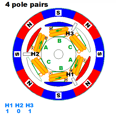
P1: BLDC motor structure
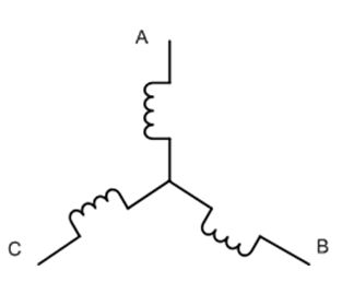
P2: Stator winding connection of a three-phase BLDC motor
Therefore, brushless DC motors require a specialized drive circuit that controls the operation of these semiconductor switches in the correct order to generate a rotating magnetic field that drives the motor to spin.
Design of A Brushless DC Motor Drive Circuit
The brushless DC motor drive circuit consists of several key components:Rotating position sensor:
The assembly includes a Hall sensor for detecting the N and S poles of the rotor magnet.
Position detection circuit:
This circuit is responsible for converting the signal of the Hall sensor into a digital logic signal.
Logic circuit:
Based on the input from the rotor position detection sensor, the circuit generates a sequence that controls the direction of the current flowing through each coil.
Pre-Drive circuit:
The circuit converts a sequential signal into a signal that triggers a semiconductor switch.
Semiconductor switch:
Six semiconductor switches are usually used. These switches open and close in response to a sequential signal to regulate the current required for the motor to rotate.
Motor drive power supply:
An external power source is required to provide current through the motor coils and to power the logic and sensor circuits. Brushless DC motors, despite the need for a drive circuit, offer superior performance without the noise and short lifespan problems associated with brushless DC motors.
Sensor and Sensorless Control in Brushless DC Motors
Two main technologies provide position feedback solutions for brushless DC motors. The first, and most common, is to integrate three Hall effect sensors in the stator at uniform intervals (usually set to 60° or 120° spacing). The second method, called “sensorless” control, is particularly suitable for brushless DC motors that seek to minimize electrical connections.
In a brushless DC motor equipped with sensors, each Hall effect sensor is coupled to a switch that generates a logic signal, one extremely “high” and the other extremely “low.” The commutation sequence is determined by the combination of logical signals generated by the Hall effect sensor and its associated switches. At any given moment, at least one sensor is triggered by one pole of the rotor, resulting in the generation of a voltage pulse.
Two Types of DC Motor Voltage Control Methods
There are two ways to change the voltage of a DC motor: PWM and PAM.
Pulse Width modulation (PWM):
PWM stands for pulse width modulation. This method involves applying voltage to a DC motor in the form of pulses. By modulating the pulse width (duty cycle), the voltage of the motor (average voltage) can be changed.
PWM is implemented in a relatively simple circuit configuration and is commonly used in DC motors.
Pulse amplitude modulation (PAM):
PAM stands for pulse amplitude modulation. This method changes the voltage applied to the motor by modulating the voltage level of the pulse.
Compared with PWM, the circuit structure of PAM is more complex. It is commonly used in large DC motors, especially those driven by high voltage or operating at 100,000 rpm or higher, to improve the efficiency of these motors.
Summary
Driving brushless DC motors, which do not use commutators and brushes, requires electronic control rather than mechanical mechanisms. This is achieved by using a motor drive circuit that includes components such as a rotary position sensor, a position detection circuit, a logic circuit, a pre-drive circuit, a semiconductor switch, and a motor drive power supply. Anyone involved in building electronic devices that contain brushless DC motors needs to have a deep understanding of the function of each component. We hope the information provided here is useful.
Electronic commutation of brushless DC motors requires precise control, which increases the complexity and cost of motor circuits. However, the rewards in terms of efficiency, such as reduced power consumption, improved reliability, space savings and reduced weight of the end product, more than offset these drawbacks. In addition, a variety of proven integrated brushless DC motor drivers significantly simplify the design process while increasing design flexibility for fine-tuning specific applications.

FAQ
Do Brushless DC Motors Require A Controller?
DC Motor Controllers: Brushed vs. Brushless
Both brushed and brushless DC motors utilize a controller that enables motor activation, speed and torque adjustment, and various other functionalities. However, controllers play a more critical role in the context of brushless DC motors, as they are an integral part of the commutation process, which is essential for all DC-powered motors.
Rescoure:
www.us.aspina-group.com


