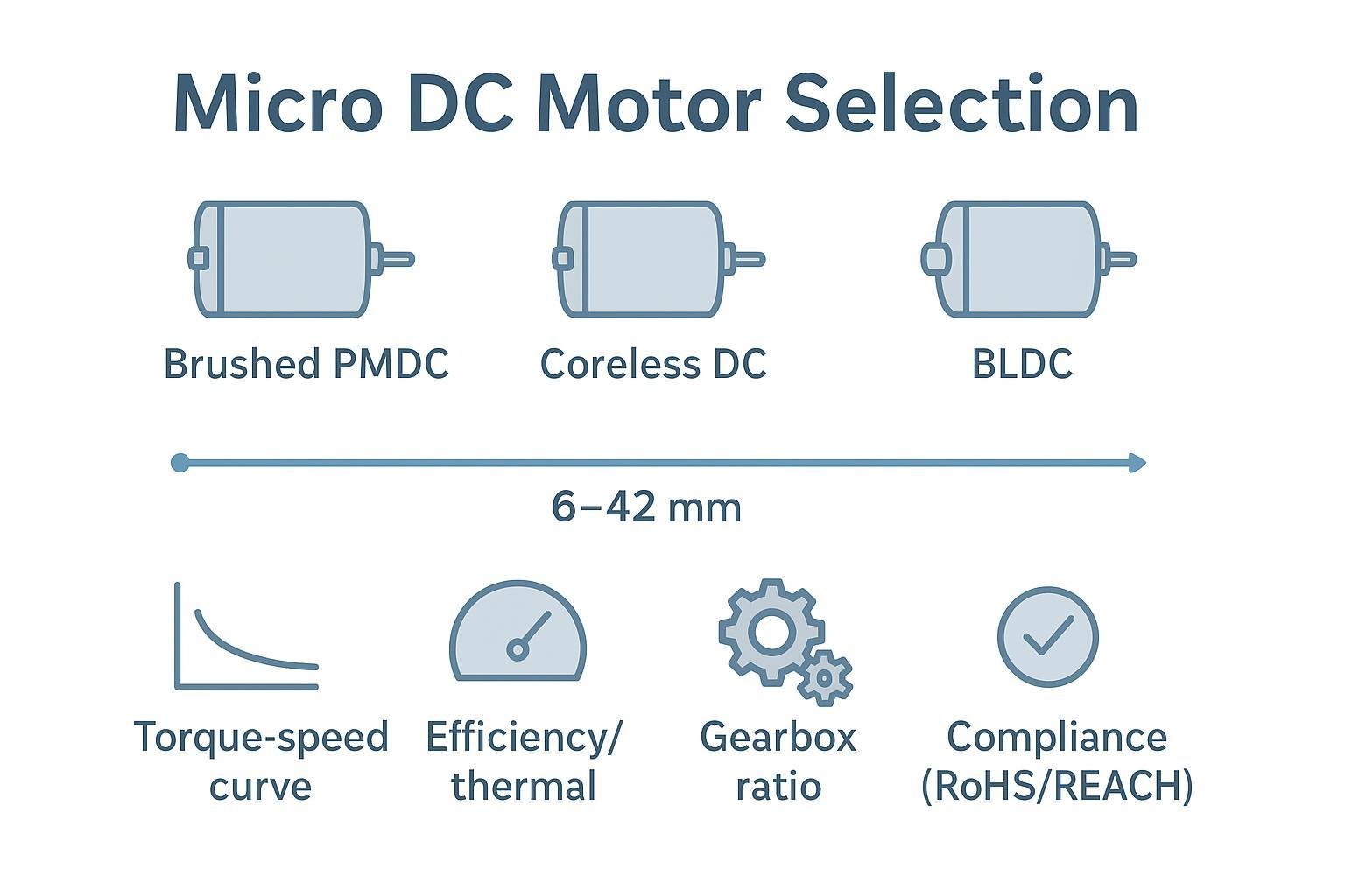
What Is A DC Gear Motor?
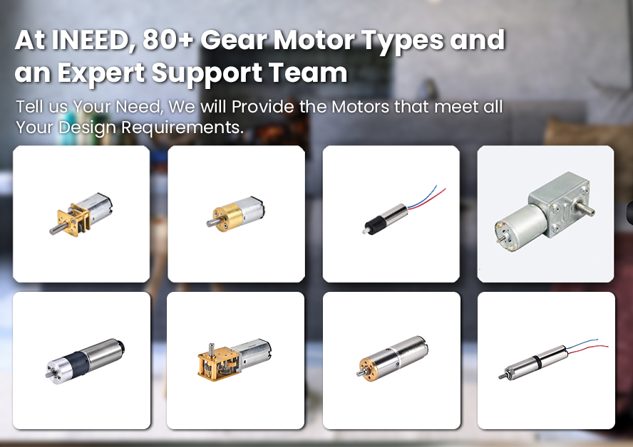
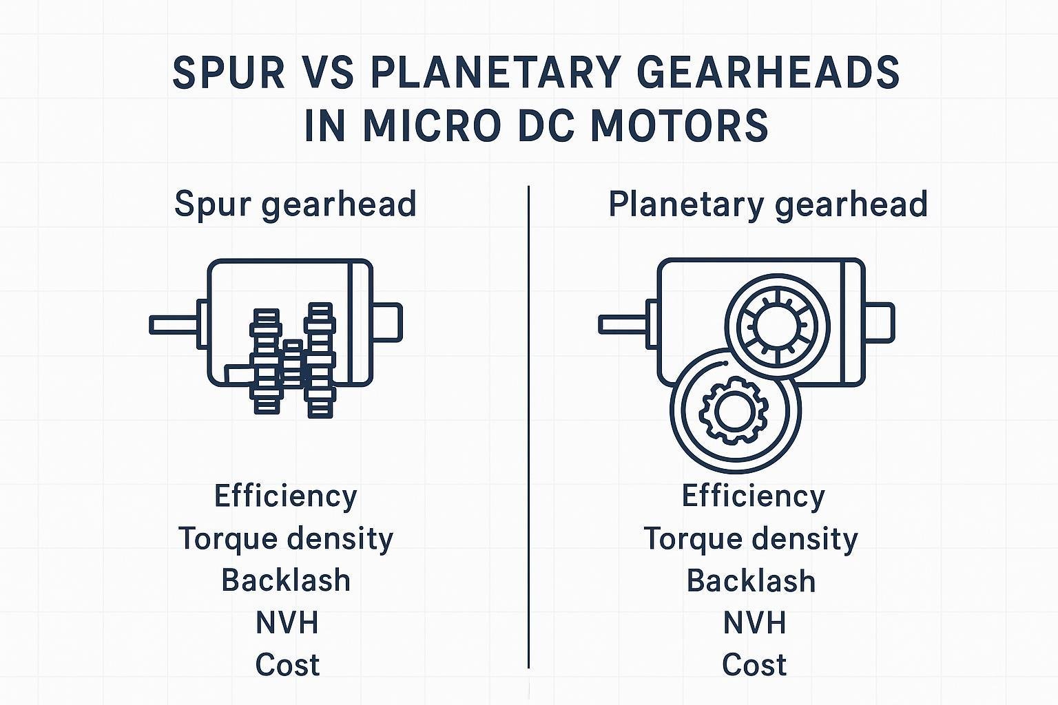
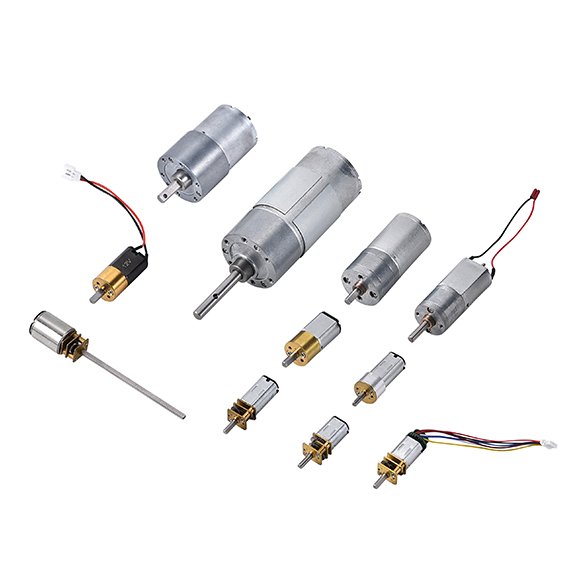
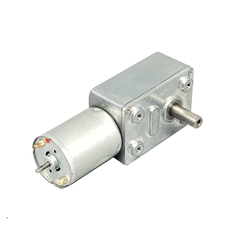
A DC gear motor, also known as a DC geared motor or a small gear motor, is a comprehensive motor system composed of a DC motor and gearbox. The main function of the DC gear motor system is to limit the speed of the DC motor shaft, and increase the output torque of the motor. The key performance parameters of a gear motor include output speed (usually measured in revolutions per minute (RPM)), output torque (usually expressed in N.m, kgf.m, or lb-ft), and efficiency (usually expressed in percentages (%)). To select the most suitable gear motor component for a particular application, it is necessary to calculate the load of the application, the required speed, and the torque. INEED Electronics has many types of gear motor, such as spur gear motors, planetary gear motors, and worm gear motors, each type suitable for different application scenarios. These motors are commonly used in modern machinery and mechanisms, provide efficient and low-noise operation, and can operate in a voltage level range from 3V to 24V. In addition, DC gear motors are a unique type powered by direct current, effectively reducing speed while enhancing torque output. In summary, the gear motor is an important electromechanical integrated system designed to meet the speed and torque requirements of a variety of applications, available in a variety of types and configurations.
How Does The DC Gear Motor Work?
Before delving into their practical applications, it is essential to understand the operation of DC gear motors. As the name suggests, DC gear motors are driven by direct current. Once the DC gear motor is properly connected, it effectively reduces the output speed while increasing the output torque. Simply put, the addition of a gearbox to a DC unit component results in a reduction in speed, which amplifies the torque output. The torque in the DC gear motor is achieved through the interconnection of the gears in the gearbox structure. Obviously, the main function of the DC gear motor is to drive the final shaft at a slower speed than the motor itself. As the speed decreases, the DC motor changes to a high-torque geared DC motor, capable of applying greater torque to the shaft or the object being rotated. Its operation depends on the rotation of the rotor, caused by the current passing through the commutator, occurring within the magnetic field. This rotational force is used to do mechanical work.
What Is Gearbox Ratio?
Gear Ratio:
The transmission ratio of a gear train is defined as the ratio between the angular speed of the input gear and the angular speed of the output gear.
How to calculate transmission gear ratio?
Transmission ratio = number of teeth of driven gear/number of teeth of driving gear
This formula provides the ratio of size or teeth between the driven gear (the gear connected to the output) and the drive gear (the gear connected to the input). This ratio helps determine how to change speed and torque in the gear system.
i = n1, n2 = D2 / D1, i = n1, n2 = z2 / z1.
i stands for transmission ratio or gear ratio
n1 indicates the speed of the drive gear
n2 indicates the speed of the driven gear
D2 Indicates the diameter of the driven gear
D1 is the diameter of the driving gear
Z2 indicates the number of teeth of the driven gear
Z1 is the number of teeth of the driving gear
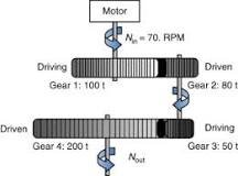
Multistage gear:transmission:
The transmission ratio between each shaft is calculated according to the above formula:
From the first axis of the total transmission ratio of n axis according to the following formula: the total transmission ratio = (Z2 / Z1) * (Z4 / Z3) * (Z6 / Z5) = (n1 / n2) * (n3 / n4 * (n5 / n6).
How is motor RPM measured?
Usually, we use a Multi-functional test meter to measure the speed of a DC gear motor. Simply connect a micro DC motor to a power source to measure speed. The principle is based on the operation conditions of DC motor, and the rotation speed of micro-DC motor is measured by extracting the speed pulse signal.
When the micro DC motor is working, the DC power is introduced into the commutator of the motor through the brush. When the micro DC motor rotates, the commutator converts the external DC voltage and current into the potential and current inside the coil, resulting in a pulse signal in the supply current loop. These pulse signals are used to determine the speed of the micro DC motor.
How Is Gearbox Power Calculated?
Motor power =(torque ÷ 9550) ×(motor power input speed ÷ deceleration ratio)÷ service factor.
In this formula:
Torque is the output torque of the gearbox.
The motor power input speed is the speed at which the motor drives the gearbox.
The reduction ratio is the gear reduction ratio of the gearbox.
The service factor is a factor that takes into account various efficiencies and losses in the system.
By inserting the appropriate values for torque, motor power input speed, reduction ratio and use factor, you can calculate the motor power required for a specific application involving the gearbox.