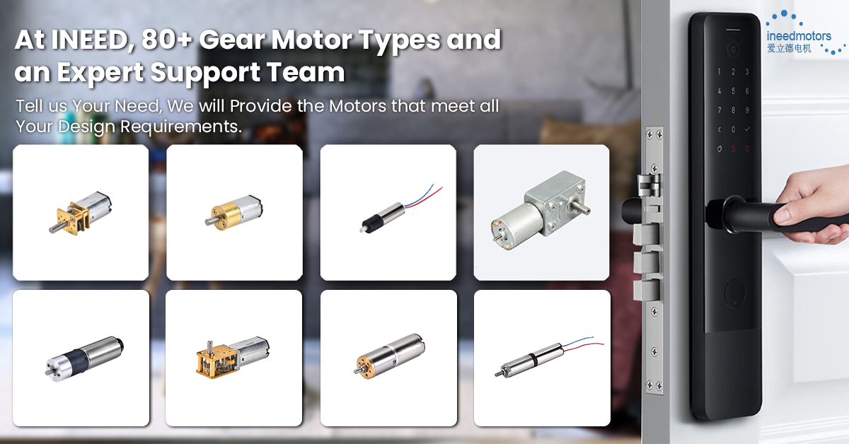
A brushless motor diagram shows you how the parts connect. It helps you see how brushless direct current systems work. The diagram shows every part and wire. This makes it easier to install and fix problems. You can find the main brushless motor advantages by using the right wiring for bldc setups.
You stop mistakes that could hurt your brushless motors for drones or other uses.
You check wires and ESC settings fast.
You change delta or wye wiring to get the best bldc motor performance.
You control heat and power for brushless motors for drones by using the diagram.
If you want your brushless motor to work well, you need to know how to read the brushless motor diagram.
Key Takeaways
Brushless motor diagrams help you see how parts and wires connect. They help you put in and fix motors the right way.
Knowing the difference between delta and wye wiring helps you pick the best setup. This is important for speed or torque needs.
The three-phase system gives power to the motor in a smooth way. It sends current in order to spin the rotor.
Electronic speed controllers and sensors work together to control the motor. They help set the speed and direction exactly.
Always check the wiring and sensor connections with the diagram. This helps you avoid mistakes and keeps your motor safe.
Brushless Motor Diagram Overview
Key Parts in a Brushless Motor Diagram
Every brushless motor diagram has some main parts. These diagrams show how each part connects in the system. The most important parts are always there, no matter who makes the motor. Here is what you will see:
The brushless motor is the main part of the system.
The electronic speed controller (ESC) controls how fast the motor spins.
Power supply connections bring electricity to the system.
Hall effect sensors are sometimes shown for better control.
You will also see three-phase connections called A, B, and C. These show how the ESC wires connect to the motor windings. Some diagrams show delta or wye setups. Each setup changes how the motor works.
What the Diagram Shows
A brushless motor diagram shows both electrical and mechanical parts. You can tell them apart by looking at their symbols and shapes. Electrical parts like coils, sensors, and wires use special symbols. For example, U, V, and W stand for the three stator wires. Plus and minus signs show which way the current goes. Sometimes, colors help you tell wires apart, but colors can mean different things.
Mechanical parts like the rotor and stator are shown as labeled shapes. Sensor wires often have three lines: power, ground, and signal. This helps you see which parts use electricity and which parts move.
There are different types of diagrams for bldc motors. The table below lists the most common types and what makes each one special:
Brushless Motor Diagram Type | Description | Key Characteristics |
|---|---|---|
Wye (Star) Configuration | Three windings meet at a center point to make a ‘Y’ shape | Gives high torque at low RPM; phase-to-neutral voltage is the same in all legs; parallel circuit |
Delta Configuration | Windings connect in a triangle shape | Has lower torque at low RPM but higher top RPM; series circuit |
Electronic Commutation Diagrams | Uses six-step commutation with sensor feedback | Uses Hall effect sensors or back EMF to find rotor position; replaces brushes; controls rotor speed with PWM |
Tip: When you look at a brushless motor diagram, check the wiring symbols and labels first. This helps you understand the connections and the setup in your bldc system.
Brushless Motor Components
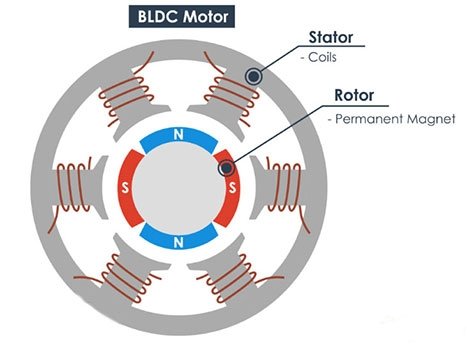
Stator and Rotor
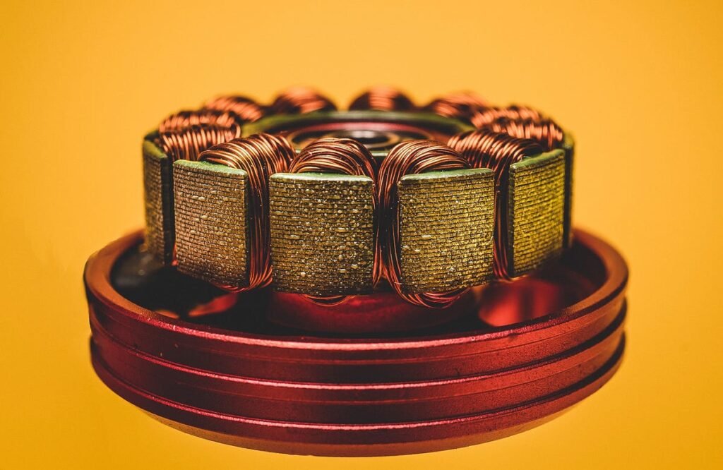
Every brushless motor has two main parts. These are the stator and the rotor. The stator does not move. It holds the coils called windings. When you give power to the stator, it makes a spinning magnetic field. The rotor sits inside the stator and spins around. It has permanent magnets on it. These magnets react to the stator’s magnetic field. This makes torque and turns the motor shaft.
The stator has the windings and makes the spinning magnetic field.
The rotor has permanent magnets and spins inside the stator.
Both parts work together to change electrical energy into movement.
Brushless motor diagrams show these parts clearly, so you can see how the motor works.
There are two types of brushless motor setups. Inrunner motors have the stator around the rotor. Outrunner motors have the rotor around the stator.
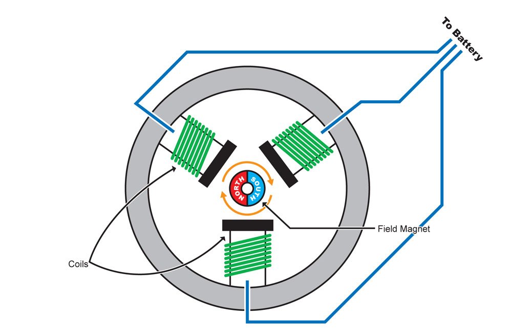
Windings and Magnets
Windings and magnets are important for making the brushless motor work. The windings are in the stator and get powered in a certain order. This makes a spinning magnetic field. The magnets are on the rotor and are often made from neodymium. When the stator windings turn on, they push and pull the rotor magnets. This makes torque and spins the rotor.
How you place the windings and magnets changes how well the motor works. If the magnets are close together and all the same size, the motor runs smoother and better. The way the windings are set up also matters for how the motor works. You can see these things in most bldc motor controller diagrams.
Sensors and ESC
Sensors and the electronic speed controller help control the motor. Most brushless motors use three Hall sensors to find the rotor’s position. These sensors are spaced 120 degrees apart. They help the controller know where the rotor is every 60 degrees. Some motors do not use sensors. They use back emf to find the rotor’s position instead.
The esc connects to the motor windings and sensors. It gets power and control signals. Then it sends the right current to each phase. The esc uses feedback from the sensors to control speed and direction. In a bldc motor controller diagram, you see the esc connected to the motor, sensors, and power supply. The controller makes sure all parts work together for smooth running.
Tip: Always check the wires and sensor spots in your bldc motor controller diagram. This helps you avoid mistakes and keeps your brushless motor working well.
Brushless Motor Wiring Diagram
Delta and Wye Configurations
When you look at a brushless motor wiring diagram, you will see two main ways to connect the wires. These are called delta and wye (star) configurations. These show how the windings are joined inside the motor. You can tell which is which by looking at the shapes in the diagram.
Delta wiring links the three phases in a triangle shape. Each corner is a connection point called A, B, or C. This setup does not have a neutral point.
Wye wiring joins one end of each winding to a center spot called the neutral. The other ends go to A, B, and C. This makes a ‘Y’ shape in the diagram.
Here is a quick comparison:
Configuration | Diagram Shape | Connection Points | Main Features |
|---|---|---|---|
Delta | Triangle | A, B, C | Faster speed, less torque, more heat, higher Kv, can be noisy at low speeds |
Wye (Star) | ‘Y’ or Star | A, B, C, Neutral | More torque at low speed, smoother running, lower Kv, good for most uses |
You use delta wiring if you want your brushless motor to go faster. This setup gives you a higher Kv, about 1.7 times more than wye. Delta motors can get hotter and use more power. They might make more noise and heat up at low speeds because of extra currents. Wye wiring gives more torque at low speeds and smoother spinning. It avoids the extra heat and noise that delta motors can have. Wye wiring is better if you need smooth starts and steady power.
Tip: Always check the brushless motor wiring diagram to see which setup you have before you connect anything. This helps you pick the right one for your needs and keeps your system safe.
The wiring setup you choose changes how your motor works. Delta wiring lets you reach higher speeds but can cause early magnetic problems and more current ripple. Wye wiring spreads the current out more, which helps avoid early problems and keeps the motor running smoothly. Both setups can give you about the same torque if you change the phase currents, but they handle current and voltage in different ways. Wye wiring lowers the starting current and torque, which helps when starting heavy things. Delta wiring gives full torque right away but can stress the motor if not handled well.
Three-Phase System
A brushless motor wiring diagram always shows three main wires for the phases. These wires are called A, B, and C. The three-phase system is very important for the brushless motor. Each phase wire carries current that is 120 degrees apart from the others. This setup makes a spinning magnetic field that pulls the rotor around.
You see three-phase wiring in both delta and wye setups. The wiring diagram shows how the controller switches current between the phases. The bldc motor controller uses a six-step sequence. It powers two of the three phases at a time. This makes the magnetic field spin and turns the rotor. The three-phase system gives smooth and efficient motor running. It also helps save energy and means you do not need extra starting parts.
Most brushless motor wiring diagrams also show wires for Hall sensors. These sensors tell the controller where the rotor is. The bldc motor controller uses this to know when to switch the phases. It is important to wire both the phase wires and sensor wires correctly. If you mix up the wires, you can get problems like strange running, extra heat, noise, or even the motor spinning backward. You might also see shaking or poor running if the wiring is wrong.
Note: Always double-check your brushless motor wiring and sensor wires. Good wiring and correct sensor spots keep your system working well and help avoid damage.
The three-phase system in the brushless motor wiring diagram shows how current moves through each phase. The diagram helps you see how the phases work together. The right phase order makes sure the motor spins the right way. If you swap two phase wires, the motor will spin the other way. The wiring diagram also helps you find wiring mistakes that can hurt how well your motor works.
Here is a summary of what you see in a normal brushless motor wiring diagram:
Three phase wires (A, B, C) for power
Sensor wires for detection (usually five wires)
Clear labels for delta or wye setups
Connections to the bldc motor controller
Symbols that show how current flows and the phase order
A good brushless motor wiring diagram helps you understand how the brushless motor works and keeps your system running well. You can use the diagram to check your wiring, make things work better, and make sure your bldc motor controller gets the right signals.
How to Read a Brushless DC Motor Diagram
Installation Steps
When you start with a brushless dc motor diagram, you need to know what each symbol means. The most important symbols help you find the right wires and parts. Here are the key symbols you should look for:
Motor phase symbols (U, V, W) show the three stator windings.
Hall sensor symbols mark the sensors that track rotor position.
The ESC symbol points to the electronic speed controller.
Other wiring symbols show power, switches, capacitors, and relays.
You should always match these symbols to the real parts before you make any connections. If you follow the diagram, you can avoid common mistakes. Some of the most frequent errors include:
Incorrect motor alignment, which causes vibration.
Poor motor support, leading to bad power quality.
Not following the manufacturer’s instructions, which can cause motor failure.
Wrong wiring between the motor, bldc motor controller, and power source, which leads to startup problems.
Tip: Always double-check the wiring order and make sure the bldc motor controller matches the diagram. This step helps you avoid wiring errors and keeps your system safe.
Troubleshooting Tips
If your brushless dc motor does not work as expected, you can use the wiring diagram to find the problem. Start by checking all wiring connections against the diagram. Make sure the phase wires and sensor wires go to the right spots on the bldc motor controller.
Here is a simple troubleshooting process:
Use a multimeter to check the resistance across each motor winding. The values should be almost the same.
Test the Hall sensors by pulling each output up to 5 volts and spinning the motor by hand. Watch for signal changes.
Use an oscilloscope to check for switching signals on each phase wire.
Measure the voltage at the motor terminals. It should be within 10% of the rated value.
Listen for strange noises or feel for heat when you spin the motor. These signs can point to winding shorts or mechanical issues.
You should also check the bldc motor controller for error codes or damaged parts. Make sure the controller mode matches your motor. If you find loose wires or bad connectors, fix them before running the motor again.
Note: The wiring diagram is your best tool for finding and fixing faults. It helps you trace every wire and test each part step by step.
If you know how to read brushless motor diagrams, you can make things work better and fix problems in many ways. You can find wiring mistakes, pick the right parts, and help your brushless motor work its best. Real-life examples show that reading diagrams the right way helps you build better systems and keeps them running well. If you want to learn more, check out these resources:
Resource Type | Description |
|---|---|
Detailed Guide | Find out how brushless motors work, how to wire them, and how to control them for different jobs. |
Diagrams | Look at block diagrams and schematics to practice and learn. |
Expert Guidance | Get tips from engineers about picking motors and putting systems together. |
Send us your load, voltage and RPM target—our engineers will recommend a BLDC + ESC wiring and provide a datasheet.
FAQ
What does a brushless motor diagram show you?
A brushless motor diagram shows you how each part connects. You see the wiring, the controller, and the sensors. The diagram helps you understand how the motor works and how to set it up.
What is the difference between delta and wye wiring?
Delta wiring connects the windings in a triangle. Wye wiring joins them in a “Y” shape. Delta gives you higher speed. Wye gives you more torque at low speed. You pick the setup based on your needs.
What do the three phase wires do in a brushless motor?
The three phase wires carry power to the motor. Each wire sends current at a different time. This creates a spinning magnetic field. The field makes the rotor turn and gives you smooth motor movement.
What should you check first if your brushless motor does not work?
Always check the wiring connections first. Make sure each wire matches the diagram. Look for loose or broken wires. Check the controller settings. Fix any mistakes before you run the motor again.