You can achieve seamless PCB integration by customizing the output shaft and wires of the gear motor. Selecting the right motor ensures reliable performance and fits your application’s requirements. When you match the output shaft and wires of the gear motor to your PCB, you improve both mechanical and electrical compatibility. This process increases stability, enhances efficiency, and supports long-term durability for your project.
Key Takeaways
Customize the output shaft and wires of your gear motor to ensure seamless PCB integration and reliable performance.
Measure and modify the output shaft dimensions accurately to fit your PCB, preventing issues during assembly.
Select the right wires for your motor based on current and voltage needs, and keep wiring short to reduce resistance.
Secure the motor with stable fixtures to minimize vibration and protect your PCB from damage during operation.
Test your motor and PCB integration thoroughly to identify and resolve any issues before final assembly.
Assessing Integration Needs for Output Shaft and Wires of the Gear Motor
Mechanical and Electrical Requirements
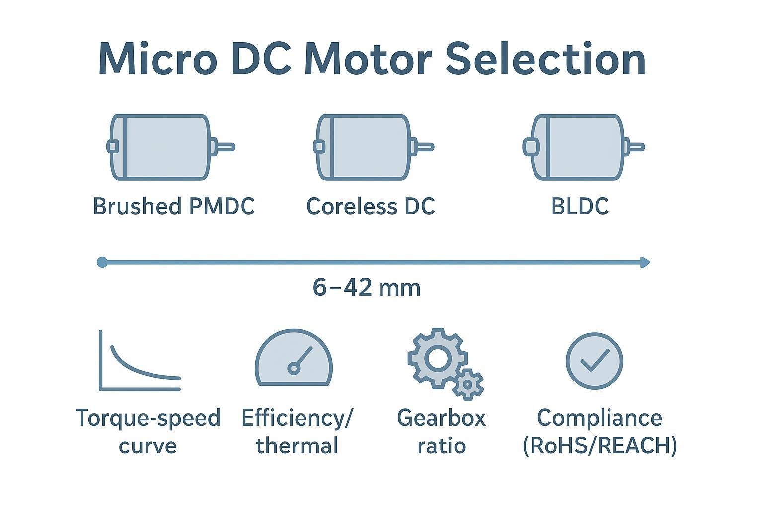
Before you begin customizing the output shaft and wires of the gear motor, you need to understand the specific requirements of your project. Start by looking at both mechanical and electrical factors that affect how well the motor will work with your PCB.
Torque requirements: You should know how much force your application needs. This helps you pick the right gearhead and motor size.
Speed range: Decide the speed you want the gear motor to run. This ensures your device works as planned.
Power supply compatibility: Check that the voltage and current match your power source and PCB.
Environmental conditions: Think about temperature, humidity, dust, or chemicals that could affect the motor’s life.
Size and mounting: Make sure the gearhead and motor fit your PCB and mounting points.
Efficiency and energy consumption: Choose energy-efficient motors to save power and reduce heat.
Control features: Decide if you need sensors, feedback, or speed controls for your application.
You should write down these requirements before you select a motor. This step helps you avoid problems later in the design process.
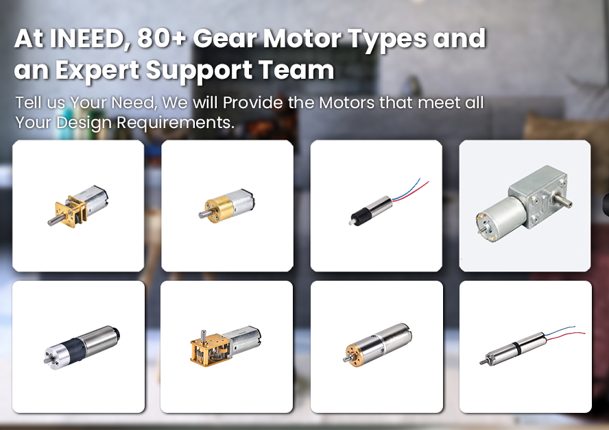
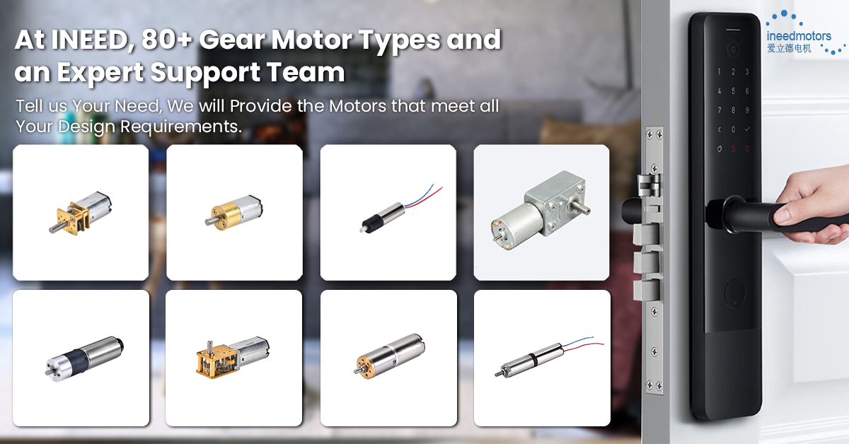
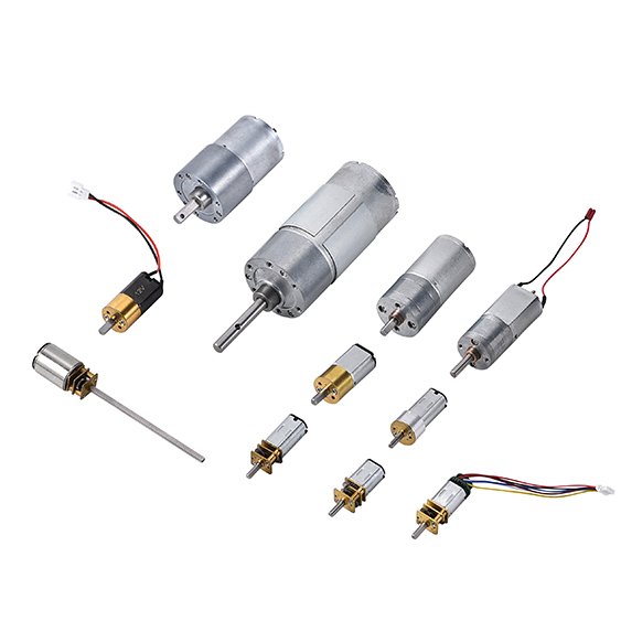
Selecting INEED Small Gear Motor Solutions
INEED Motors gives you many options for customizing your gear motor. You can choose the right gearhead, shaft, and wiring to match your PCB. The table below shows how INEED’s small gear motors compare to other brands when it comes to customization:
INEED Small Gear Motors | Other Brands (General) | |
|---|---|---|
Custom Reduction Ratio | Yes | Varies |
Material Options (Steel/Brass) | Yes | Limited |
Specific Voltage Ratings | Yes | Varies |
Tailor-Made Stall Torque | Yes | Limited |
You can select the reduction ratio, shaft material, and voltage that best fit your PCB. INEED also lets you tailor the stall torque and gearhead type for your project. This flexibility makes it easier to achieve a perfect match between the output shaft and wires of the gear motor and your PCB design.
Output Shaft Customization for PCB Integration
Measuring and Modifying Shaft Dimensions
You need to measure the output shaft and wires of the gear motor before you start any customization. Use a digital caliper or a micrometer to get accurate measurements of the shaft diameter, length, and shape. Write down these numbers so you can compare them with the mounting holes and slots on your pcb. If the shaft does not fit, you can modify it by trimming, extending, or replacing it with a custom part.
You can choose a round, D-shaped, or keyed shaft depending on your application. A D-shaped shaft gives you better grip and prevents slipping. A round shaft works well for simple connections. If you need precise alignment, a keyed shaft is a good choice. You can also ask INEED Motors for a custom shaft that matches your pcb layout. Their engineering team can help you select the right gearhead and shaft combination for your project.
Here is a simple checklist to guide you:
Measure shaft diameter and length.
Check shaft shape and compatibility with your pcb.
Decide if you need to trim, extend, or replace the shaft.
Choose the right shaft type for your gearhead.
Contact INEED Motors for custom solutions if needed.
Tip: Always double-check your measurements before making any changes. Accurate measurements help you avoid costly mistakes and ensure a secure fit.
Ensuring Stability with PCB Fixtures
You must secure the output shaft and wires of the gear motor to your pcb to prevent movement and vibration. Use mounting brackets, screws, or clips to hold the motor in place. Make sure the gearhead aligns with the pcb holes and slots. If you use a custom fixture, test it for stability before final assembly.
INEED Motors offers customization options for mounting fixtures. You can request brackets or holders that match your pcb design. Their team can help you select materials that reduce vibration and improve stability. Stable mounting keeps the motor running smoothly and protects your pcb from damage.
Here is a table showing common fixture options and their benefits:
Fixture Type | Benefit |
|---|---|
Mounting Bracket | Strong support, easy to install |
Screw Fastener | Secure hold, prevents shifting |
Plastic Clip | Quick setup, reduces vibration |
Custom Holder | Perfect fit, tailored design |
Note: Test your fixture with the motor running at full speed. This helps you spot any issues with vibration or alignment early.
When you customize the output shaft and wires of the gear motor for pcb integration, you improve mechanical stability and ensure reliable performance. INEED Motors supports you with custom gearhead and fixture solutions, making your integration process easier and more effective.
Wiring Solutions for Gear Motor and PCB
Choosing and Routing Wires
You need to select the right wires for your motor and pcb connection. Start by checking the current and voltage your motor requires. Choose wires with enough thickness to handle the load without overheating. Shorter wires work better because they reduce resistance and signal loss. Long wires can pick up noise and make your system less reliable.
When you plan your wiring, keep these points in mind:
Optimize the length of your wires. Short wires reduce resistance and inductance.
Secure all cables so they do not move or get pulled.
Avoid making unnecessary coils or loops. These can increase noise and interference.
You should also think about how you route the wires on your pcb. Good routing keeps your signals clean and your system safe. Here are some techniques you can use:
Use impedance control to keep signal quality high, especially for fast signals.
Add guard traces to protect sensitive signals from interference.
Design trace width and spacing carefully. This helps prevent wire damage and keeps signals strong.
Make sure you have proper grounding. Good grounding reduces noise and improves reliability.
INEED Motors supports you with custom wiring options. You can request wires cut to the exact length you need. Their team can help you choose the best wire type for your gearhead and motor setup.
Tip: Plan your wiring layout before you start soldering. This makes installation easier and helps you avoid mistakes.
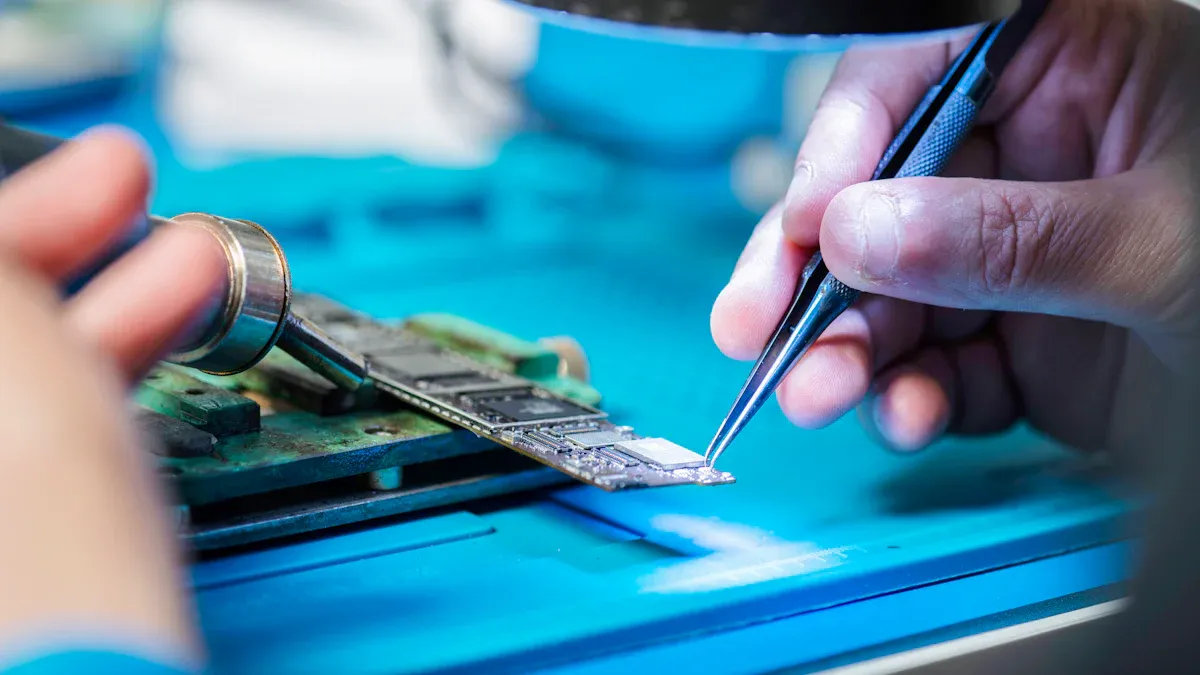
Soldering and Connector Options
You must connect the output shaft and wires of the gear motor to your pcb with care. Good soldering keeps your connections strong and reliable. Follow these best practices for soldering:
Set your soldering iron between 280-320°C (536-608°F). Hold the iron on each joint for only 3-5 seconds.
Use just enough solder to cover the pad and wire. You want a small, shiny joint with no extra buildup.
Clean your soldering iron tip often. This helps you make better joints.
Check your work. Look at each joint and use a multimeter to test for good connections.
Take your time. Align each wire and pad before you add solder.
You can also use connectors instead of soldering. Connectors make it easy to remove or replace the motor. Choose connectors that fit your gearhead and pcb design. INEED Motors offers custom connector options to match your project needs.
Strain relief is important for durability. It protects your wiring from stress and bending. Here is a table showing how strain relief helps your connections:
Benefit | Description |
|---|---|
Reduces mechanical stress | Strain relief minimizes the stress on wiring connections, enhancing their longevity. |
Prevents sharp bends | The design avoids sharp bends at fragile tabs, which are common failure points. |
Modular and secure solution | The pcb design allows for a cleaner and more organized wiring setup, improving overall reliability. |
Easy to secure | Optional mounting holes make it easy to secure the board, increasing durability. |
INEED Motors can help you add strain relief features to your wiring setup. Their engineering team can suggest the best way to secure your wires and connectors for long-lasting performance.
Note: Always test your motor after wiring. Run it at full speed and check for any loose connections or noise.
You improve reliability and safety when you follow these wiring and soldering practices. Customization of your wiring and connectors ensures your gearhead and motor work perfectly with your pcb.
Building a Customized DC Motor Drive System
Integration and Testing Steps
You start building a customized dc motor drive system by connecting the output shaft and wires of the gear motor to your pcb. Begin by mounting the motor securely using the right gearhead and fixture. Make sure the wires are routed cleanly and connected to the correct pads or connectors on the pcb. After assembly, you need to validate the system’s performance.
Testing is a key part of this process. You should use several methods to check if your motor and pcb work together as planned. The table below shows common testing procedures:
Testing Procedure | Description |
|---|---|
Efficiency Measurement | Calculate mechanical output power versus electrical input power using voltage and current readings. |
Thermal Monitoring | Use thermal imaging or thermocouples to keep temperatures within safe limits during operation. |
Electrical Testing | Measure voltage and current at different points to confirm they match your design. |
Mechanical Testing | Use a dynamometer for torque and an optical encoder for speed under different loads. |
Thermal Analysis | Map heat distribution and log temperatures to find hotspots. |
Vibration and Noise Testing | Measure vibration and noise to check performance and user experience. |
Endurance Testing | Simulate long-term use to validate durability by monitoring key metrics over time. |
You should record all results and compare them to your design goals. If you find any issues, adjust your motor setup or wiring and repeat the tests.
Best Practices and Common Pitfalls
You can improve the durability and safety of your customized dc motor drive system by following best practices. Use proper spacing and alignment for gold fingers to prevent misalignment and signal problems. Choose materials like FR4 for your pcb to increase durability. Inspect gold plating for evenness and thickness to ensure good conductivity. Store your pcb in anti-static bags and control the environment to extend its lifespan. Regular maintenance checks help you spot deterioration early and apply protective coatings against moisture.
Motor controllers with high efficiency ratings and advanced thermal management reduce energy use and keep your system reliable. Integrated safety features such as overcurrent protection, thermal shutdown, and rotor lock protection help prevent damage.
Watch out for common pitfalls during integration. The table below lists issues you may face:
Common Pitfall | Description |
|---|---|
Gate Driver Integration | High-side gate drivers may need isolated supplies or bootstrap circuits for power. |
Position and Current Sensing | Accurate feedback is needed for motor control algorithms. |
Digital Control Implementation | Real-time performance and noise management are important for digital circuits. |
Thermal Management | Good thermal design is needed to handle power dissipation and high temperatures. |
EMI Control | Design for EMI from the start to prevent interference in motor control operations. |
You avoid many problems by planning your integration steps and testing thoroughly. INEED Motors uses strict quality assurance to help you achieve reliable results with your gearhead and motor assemblies.
Tip: Always document your integration and testing process. Clear records make troubleshooting easier and help you improve future designs.
You can achieve reliable PCB integration by customizing the output shaft and wires of your motor. Start by measuring and modifying the gearhead, then secure the motor with stable fixtures. Choose the right wires and connectors for your motor and test everything carefully. INEED’s Small gear motor and Spur Gear Motors give you flexibility and efficiency for any project.
Factor | Description |
|---|---|
Drive Train Components | Gearbox, motor, and gearhead affect performance. |
Load Characteristics | Match the motor to your application’s needs. |
High-efficiency motors save energy and last longer. |
Automation and energy efficiency drive demand for custom motor solutions.
Future motors will use new materials and AI for better performance.
Contact INEED for technical support or custom motor solutions.
FAQ
What shaft types can I choose for my gear motor?
You can select from round, D-shaped, or keyed shafts. Each type offers different benefits for grip and alignment. INEED Motors can customize the shaft to fit your PCB design.
How do I know which wire gauge to use?
Check your motor’s voltage and current needs. Use thicker wires for higher currents. Thinner wires work for low-power applications. Always follow the manufacturer’s recommendations for safety.
Can I request custom connectors for my project?
Yes! INEED Motors offers custom connector options. You can match connectors to your PCB layout for easy installation and maintenance.
How do I prevent vibration from damaging my PCB?
Use secure mounting brackets or custom holders. Test your setup at full speed. Stable fixtures reduce vibration and protect your PCB from damage.