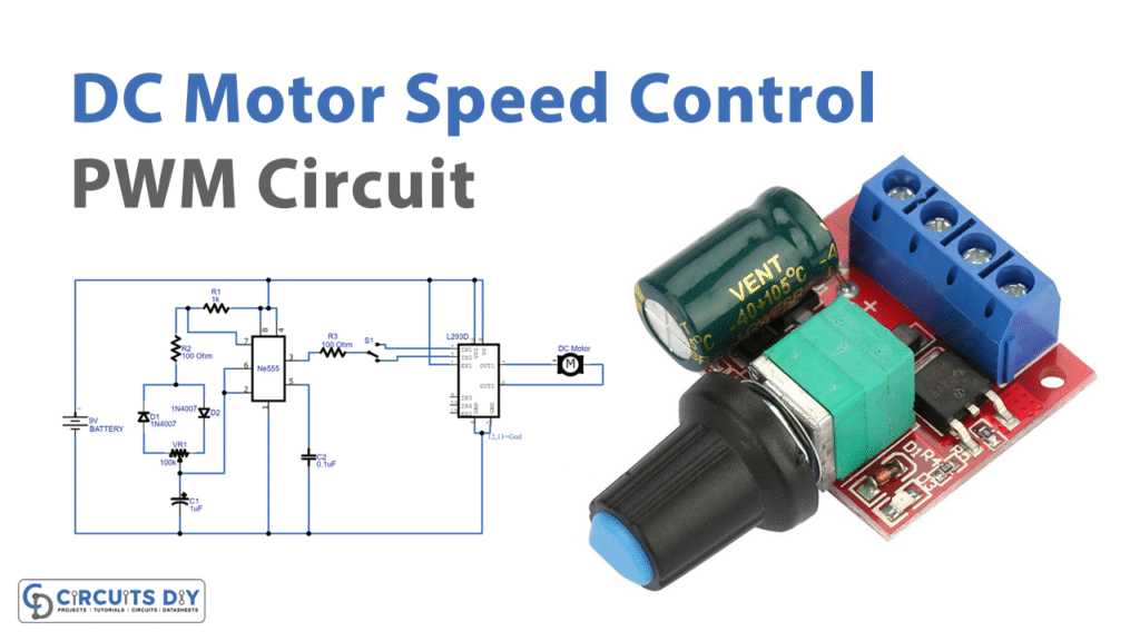
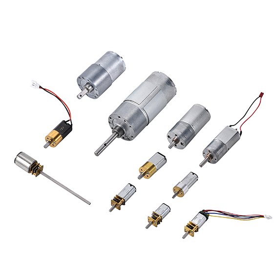
PWM motor controllers use pulse width modulation to control the speed of a motor by rapidly switching the power on and off. This method gives precise control while reducing energy loss. Engineers prefer PWM because it minimizes current ripple, which keeps the motor cooler and extends its life. The table below shows how adjusting PWM frequency and other factors can improve efficiency and motor performance:
Performance Aspect | Data / Observation | Impact on Efficiency / Motor Life |
|---|---|---|
PWM Frequency Increase | Doubling PWM rate halves peak-to-peak current ripple | Reduced current ripple lowers power dissipation, improving efficiency |
Locked Rotor Test | Higher PWM rates consistently reduce current ripple; similar performance across manufacturers | Confirms reliability of PWM frequency effect on ripple and efficiency |
Current Loop Tuning | Optimizing integral gain reduces current error by factor of 2 | Enhances control precision, reducing losses and improving efficiency |
Added Inductance | Doubling inductance achieves similar ripple reduction as doubling PWM rate | Reduces motor heating but may add losses due to resistance |
Typical PWM Frequencies | 15-20 kHz common; 30-40 kHz available; 60-100 kHz rare but dramatically reduces ripple | Higher frequencies improve efficiency but increase thermal load |
These improvements make PWM motor controllers a smart choice for anyone needing reliable speed control in motors.
Key Takeaways
PWM motor controllers control motor speed by rapidly switching power on and off, allowing precise and energy-efficient operation.
Adjusting the PWM duty cycle changes the average voltage to the motor, enabling smooth speed control without wasting energy as heat.
Higher PWM frequencies reduce current ripple and noise, helping motors run cooler, quieter, and last longer.
PWM controllers include safety features like current sensing and soft-start to protect motors from damage and improve reliability.
These controllers are widely used in robotics, electric vehicles, fans, and pumps because they offer flexible, efficient, and reliable motor control.
DC Motor Basics
How DC Motors Operate
A dc motor changes electrical energy into mechanical motion. The basic design includes a rotor, stator, brushes, and a commutator. When a dc voltage is applied, current flows through the windings. This current creates a magnetic field, which interacts with the field from the stator. The interaction causes the rotor to turn. In brushless dc motors, electronic commutation replaces brushes. A three-phase H-bridge circuit energizes the motor phases in sequence. Pulse width modulation (PWM) signals control this process. By adjusting the duty cycle of the PWM signal, the controller regulates the average voltage and current sent to the motor. This method allows for efficient speed and torque control. Compared to linear amplifiers, PWM chopper amplifiers switch power transistors on and off. This reduces power loss and heat, making the system more efficient. The fixed switching frequency of PWM also helps filter out noise, which improves performance in both brush and brushless dc motors.
A typical PWM control system for a dc motor includes several key components:
A regulated dc power supply provides consistent energy.
The PWM generator creates the square wave signal.
A feedback mechanism, such as a tachometer, measures motor speed.
Safety circuits protect against overcurrent and overvoltage.
Potentiometers and switches allow users to adjust speed and operation modes.
Importance of Speed Control
Speed control plays a vital role in dc motor applications. Many devices need the motor to run at different speeds for different tasks. Without proper speed control, a dc motor may run too fast or too slow, which can cause problems. For example, in electric vehicles, precise speed control ensures smooth acceleration and safe operation. Studies show that advanced controllers, such as fuzzy logic control, help dc motors reach target speeds faster and with less error. These controllers also keep torque steady and reduce unwanted oscillations. This leads to smoother operation, longer motor life, and better energy efficiency.
Researchers found that fuzzy logic control allows a dc motor to:
Reach target speed quickly with no overshoot.
Maintain steady torque even when the load changes.
Operate smoothly over a wide speed range.
Reduce electromagnetic noise and improve rotor position control.
Reliable speed control helps optimize performance and reliability in many dc motor systems. It also protects the motor from damage and supports stable operation in changing conditions.
Traditional Methods
Linear Control
Engineers have used linear control methods for many years to manage the speed of a dc motor. The most common approach uses a variable resistor or a linear voltage regulator. These devices change the voltage sent to the dc motor. When the voltage drops, the motor slows down. When the voltage rises, the motor speeds up. This method seems simple and easy to use. Many early machines and toys used this type of control for their dc motors.
Linear controllers like PI (Proportional-Integral) compensators and LQR (Linear Quadratic Regulator) controllers also play a role in traditional systems. These controllers work well when the dc motor operates under steady, predictable conditions. They use mathematical models that assume the motor and its environment behave in a linear way. This means the relationship between input and output stays the same across different speeds and loads.
Limitations
Linear control methods face several challenges, especially when used with modern dc motor applications. These methods often waste energy. The resistor or regulator turns extra voltage into heat, which does not help the motor. This heat can damage the dc motor over time and lower its efficiency.
Researchers have found more reasons why linear control methods do not always work well:
Linear controllers like PI and LQR use models that do not match real-world dc motor systems, which often act in nonlinear ways.
These methods struggle to handle sudden changes in load or speed, making the motor less reliable.
Linear output regulation does not consider limits on the motor’s state or input, so it cannot protect the dc motor from overload.
Many systems need full state measurements, but this is not always possible, so extra sensors or observers become necessary.
Advanced methods like sliding mode control or model predictive control handle these issues better and give the dc motor more robust and precise control.
Because of these limits, engineers look for better ways to control dc motors. They want solutions that save energy, protect the motor, and work well in many situations. This search leads to the use of pulse width modulation and modern motor controllers.
Pulse Width Modulation
PWM Principle
Pulse width modulation stands out as a key technique for controlling the speed and torque of dc motors. Engineers use pulse width modulation because it allows precise adjustment of the power delivered to a motor. Instead of sending a steady voltage, the controller rapidly switches the power on and off. The length of time the power stays on during each cycle is called the duty cycle. By changing the duty cycle, the controller can increase or decrease the average voltage that reaches the motor.
Researchers have studied why pulse width modulation works so well for motor control. They found that pulse width modulation inverters, when modeled and applied to three-phase induction motors, keep torque constant across different rotor speeds. This means the motor can run smoothly even when the load changes. Closed-loop control with pulse width modulation also improves speed regulation and keeps torque steady. The following table highlights key findings from these studies:
Key Findings | Description |
|---|---|
PWM Inverter Modeling | PWM inverters modeled and applied to 3-phase induction motors in MATLAB simulations. |
Open Loop V/f Control | Torque found constant for various rotor speeds, validating PWM’s effectiveness. |
Closed Loop V/f Control | Proportional controller in closed-loop scheme enhances speed control and maintains maximum torque. |
Transient and Steady-State Response | Analysis shows improved motor response with PWM-based control. |
Pulse width modulation also reduces unwanted harmonics in the output voltage. This leads to smoother current flow and less noise in the motor. Engineers choose pulse width modulation because it gives them reliable, flexible, and efficient control over dc motors.
Duty Cycle and Voltage
The duty cycle is the percentage of time the power stays on during each pulse width modulation cycle. This value directly controls the average voltage that the motor receives. For example, if a controller uses a 9V battery and switches the power on for 50 milliseconds and off for 50 milliseconds at a frequency of 10Hz, the average voltage delivered to the load becomes about 4.5V. This is half of the supply voltage, matching a 50% duty cycle.
Pulse width modulation allows engineers to adjust the duty cycle to set the motor speed. A higher duty cycle means more power reaches the motor, making it spin faster. A lower duty cycle reduces the average voltage, slowing the motor down. The frequency of the pulse width modulation signal also matters. If the frequency is high enough, the motor’s inductance smooths out the on-off transitions, so the motor runs smoothly without jerking.
Note: The load, such as a dc motor, often acts like a filter. It averages the rapid on-off pulses from the controller, so the motor sees a steady voltage that matches the duty cycle.
Pulse width modulation gives engineers a simple way to control voltage and speed without wasting energy as heat. This makes it a popular choice for dc motor speed control.
Efficiency Benefits
Pulse width modulation offers major efficiency benefits compared to older control methods. Traditional linear controllers waste energy by turning extra voltage into heat. Pulse width modulation, on the other hand, switches the power devices fully on or off. This reduces the time spent in high-resistance states, so less energy turns into heat.
Researchers have shown that pulse width modulation not only improves efficiency but also enhances motor performance. The following table summarizes important study aspects:
Study Aspect | Evidence Summary |
|---|---|
Control Scheme | Use of constant voltage/frequency (V/Hz) control combined with PWM technique for induction motors. |
Experimental Validation | Real-time tests show good steady-state and transient performance under PWM control. |
Harmonic Reduction | Simulation and experiments demonstrate PWM output voltage harmonics reduction, yielding near sinusoidal current. |
Torque Maintenance | MATLAB simulations confirm constant torque across varying rotor speeds using PWM inverters. |
Closed-Loop Control | Closed-loop V/f control with proportional controller improves speed regulation and torque stability. |
Power Factor Optimization | Criterion developed for optimum power factor to maximize performance under PWM control. |
Pulse width modulation also helps maintain a high power factor, which means the motor uses energy more effectively. The reduction in harmonics leads to less vibration and noise, making the motor last longer. Engineers prefer pulse width modulation for dc motors because it delivers precise control, saves energy, and extends the life of the motor.
PWM Motor Controllers

Signal Generation
PWM motor controllers use precise signal generation to control how much power a motor receives. Engineers choose pulse width modulation because it allows them to adjust the average voltage sent to the motor by changing the width of each pulse. This method works by turning the power on and off very quickly. Most controllers use a fixed signal period, such as 5ms or 10ms, and set the pulse width between 1ms and 2ms. The midpoint, 1.5ms, often represents the motor’s stop or neutral position.
The reason for using these specific timings is to ensure the motor responds smoothly and accurately. High-resolution control, with up to 4096 steps of 1 microsecond each, lets the controller make very small adjustments. This level of detail helps the motor run at exactly the right speed. Engineers also calibrate each controller to account for small timing differences, which prevents unwanted motor behavior.
Different types of PWM signal generation exist, each with its own benefits:
Single-pulse width modulation uses one pulse per cycle, making it simple but sometimes less efficient.
Multiple-pulse width modulation uses several pulses in each cycle, which reduces unwanted harmonics but increases switching losses.
Sinusoidal pulse width modulation compares a sine wave with a triangle wave to create smoother output, which helps the motor run quietly.
Selective harmonic elimination targets and removes specific unwanted frequencies, making the motor even more efficient.
Engineers select the right method based on the motor’s needs. They also choose carrier frequencies, usually between 2 kHz and 10 kHz, to balance efficiency and noise. The motor’s inductance smooths out the high-frequency pulses, so the output current looks like a steady wave. This careful signal generation is why PWM motor controllers can deliver precise and reliable motor control.
Features and Functions
PWM motor controllers include many features that help users control motors safely and efficiently. Most controllers support a wide range of voltages and currents, so they can work with different types of motors. For example, some models handle 6V to 60V and currents from a few amps up to 100 amps or more. This flexibility is important because different motors need different amounts of power.
A key part of many controllers is the H-bridge circuit. This circuit lets the controller change the direction of the current, so the motor can spin forward or backward. H-bridges also allow for braking, which stops the motor quickly when needed. Current sensing is another important feature. It helps the controller detect if the motor draws too much current, which can prevent damage from overloads.
Many PWM motor controllers include user-friendly features:
Adjustable potentiometers let users set the motor speed easily.
LED displays show the current speed, direction, or error codes.
Forward-brake-reverse switches give users full control over the motor’s movement.
Some controllers offer remote control or programmable settings for advanced applications.
These features make PWM motor controllers suitable for both beginners and professionals. The combination of safety, flexibility, and ease of use explains why so many engineers and hobbyists choose these controllers for their projects.
Applications
PWM motor controllers appear in many everyday and industrial applications because they offer efficient and precise control. In robotics, engineers use them to move arms, wheels, and grippers with exact speed and position. For example, DVD spindle devices use low-power PWM techniques to reduce heat and save energy. These devices sample terminal voltages and adjust the duty ratio using fast digital circuits, which keeps the motor running smoothly.
In electric vehicles, PWM motor controllers manage the speed and torque of the drive motors. This control ensures smooth acceleration and helps save battery power. Fans and pumps also benefit from PWM control. By chopping the power at specific intervals, the controller reduces energy use and heat loss. This method keeps the motor cool and extends its life.
Some controllers use special designs, like four-switch converters for brushless DC motors. These designs lower costs and keep the current balanced, which is important for small robots and fans. Engineers also use advanced control strategies, such as PID and fuzzy logic, to improve performance in electric vehicles and energy systems.
The wide range of applications shows why PWM motor controllers are so popular. They help save energy, protect motors, and deliver reliable performance in many fields.
Practical Considerations
Circuit Protection
Engineers choose circuit protection to keep motors and controllers safe from damage. Overcurrent can harm sensitive parts or even destroy the motor. Designers use several methods to prevent these problems:
Soft-start features limit inrush current when the system powers up. This protects components and reduces electrical noise.
Many PWM controllers include a soft-start pin, which lets users program how quickly the system ramps up.
Current sensing logic can shut off the PWM output if the current goes above a safe limit. The controller can reset itself when the current returns to normal.
Electronic circuit breakers use MOSFETs to disconnect power during overcurrent events. These breakers often have adjustable limits and delay timers.
Smart H-bridge drivers monitor current in both directions. They use sense resistors and amplifiers to detect faults, even with PWM noise present.
These features explain why modern PWM motor controllers rarely fail due to electrical faults. They help users avoid costly repairs and downtime.
Heat Management
Heat can shorten the life of a motor and its controller. High current and frequent switching cause parts to warm up quickly. Good heat management keeps the system running smoothly. Engineers use heat sinks, fans, and thermal pads to move heat away from sensitive parts. Some controllers include temperature sensors that shut down the system if it gets too hot. This protects the motor from overheating and prevents permanent damage. Proper heat management explains why motors last longer and perform better in demanding applications.
Tip: Place the controller in a well-ventilated area and check for dust buildup on cooling fins. Clean parts regularly to keep airflow strong.
Frequency and Noise
PWM frequency affects both the sound and performance of a motor. When the controller switches power on and off, it creates harmonics in the voltage and current. These harmonics can cause extra magnetic forces inside the motor. Sometimes, these forces excite resonances in the motor structure, which leads to more noise. The noise depends on the frequency and the speed of the motor. Choosing the right PWM frequency helps avoid these problems.
Research shows that higher PWM frequencies can move noise outside the range people can hear. For example, using advanced technology, engineers have pushed PWM frequencies up to 100 MHz. This shift reduces audible noise and makes the motor run more quietly. However, higher frequencies can also increase heat, so designers must balance noise reduction with thermal management. Selecting the correct frequency explains why some motors run quietly while others make a noticeable whine.
Tips for Hobbyists and Engineers
Always check the current rating of your controller and motor before connecting them.
Use fuses or electronic breakers for extra safety.
Monitor temperature during long runs.
Test different PWM frequencies to find the quietest and most efficient setting for your motor.
PWM motor controllers give users many reasons to choose them for projects. They help each motor run cooler, last longer, and use less energy. Engineers see that these controllers work well in robots, vehicles, and fans. The precise speed control lets a motor perform tasks smoothly. People who want reliable motor performance should try PWM motor controllers. These devices show why modern motor technology keeps improving.
FAQ
Why do engineers prefer PWM motor controllers over linear controllers?
Engineers choose PWM motor controllers because they waste less energy. PWM switches power on and off quickly, which keeps motors cooler and saves electricity. Linear controllers turn extra energy into heat, which can damage motors and lower efficiency.
Why does PWM frequency affect motor noise?
PWM frequency changes how often the controller switches power. Higher frequencies move noise above what people can hear. This makes motors run more quietly. Lower frequencies can cause motors to make a whining sound.
Why is current sensing important in PWM motor controllers?
Current sensing protects the motor and controller from damage. It helps detect if the motor draws too much current. The controller can then shut off power or reduce speed to prevent overheating or failure.
Why do many applications use H-bridge circuits in PWM controllers?
H-bridge circuits let the controller change the direction of the motor. This allows motors to spin forward or backward. Many robots, vehicles, and machines need this feature for full movement control.
Why should users adjust the duty cycle when controlling motor speed?
Adjusting the duty cycle changes how much power the motor receives. A higher duty cycle makes the motor spin faster. A lower duty cycle slows it down. This gives users precise control over speed for different tasks.
