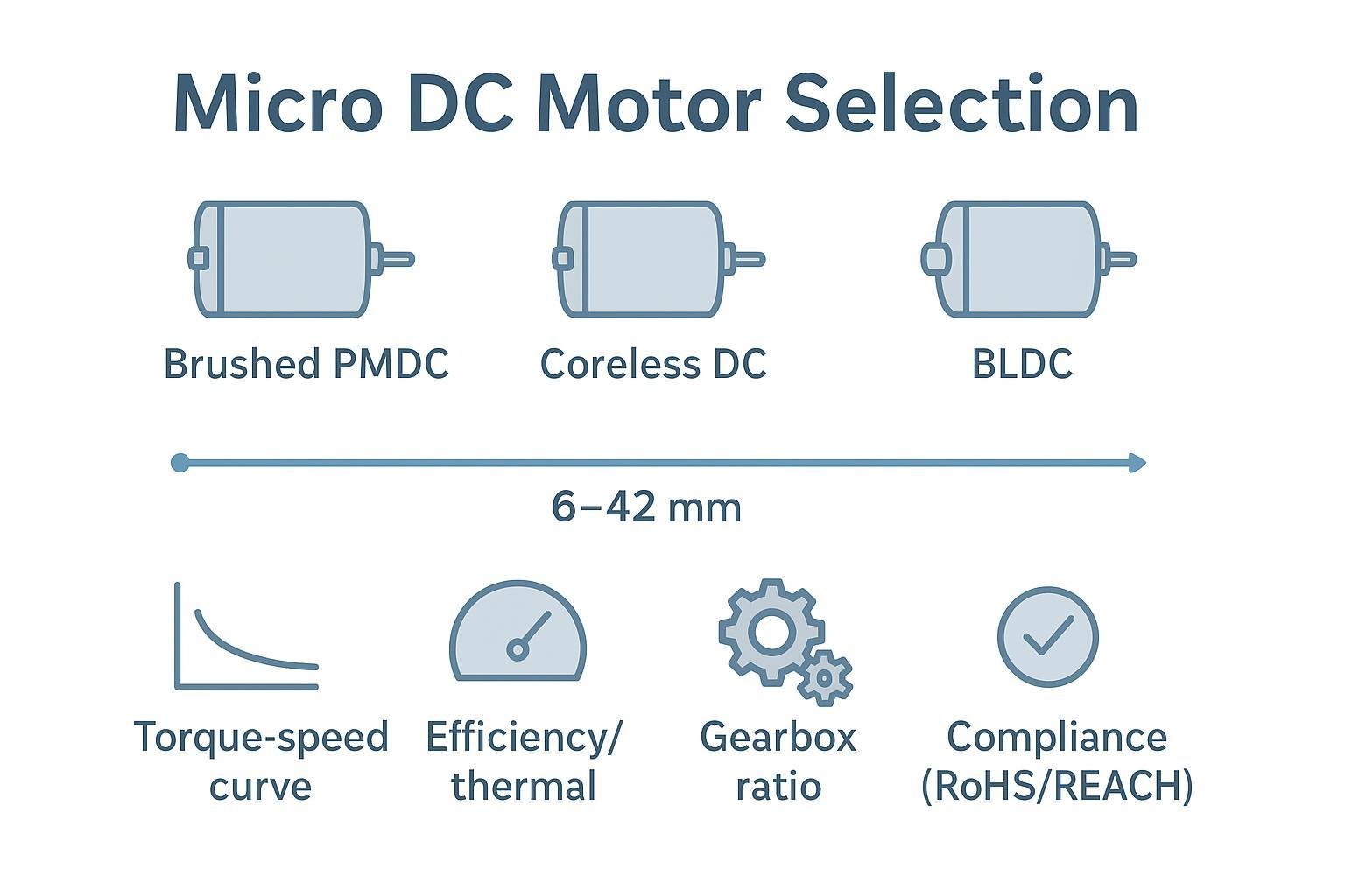
Introduction
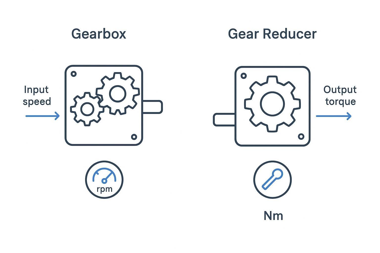
In sourcing conversations, “gearbox” and “gear reducer” often get used interchangeably. When the spec is fuzzy, gear reducer vs gearbox confusion can turn into a real cost: the wrong ratio, the wrong efficiency assumption, the wrong backlash requirement, or a housing/layout that simply doesn’t fit your envelope.
The simplest hierarchy that avoids confusion is this: a gear reducer (often called a speed reducer—you’ll also see it described as speed reducer vs gearbox in supplier catalogs) is a gearbox used specifically for speed reduction and torque multiplication. A gearbox is the broader category—some gearboxes reduce speed, some increase speed, and some primarily change direction.
That distinction isn’t just semantics. It drives quantified differences that matter for sizing and life:
Efficiency and heat: a few percentage points of loss can become a thermal problem in small, enclosed assemblies.
Backlash vs real positioning error: backlash alone rarely tells the full story; torsional compliance and load also matter.
Stage count and duty cycle: higher ratios often mean more stages, which can compound losses and affect stiffness.
The rest of this guide keeps the terms straight, compares the main reducer families, and then gives you a practical selection flow—ending with documentation and compliance checks that reduce qualification surprises.
Definitions and scope
What is a gear reducer?
If you’re searching “what is a gear reducer,” the short answer is: it’s a gearbox used specifically for speed reduction and torque multiplication at a defined ratio. In many catalogs, you’ll also see it described in “speed reducer vs gearbox” terms—where “speed reducer” is simply a reducer-focused use case under the broader gearbox umbrella.
What is a gearbox?
A gearbox is a mechanical transmission that uses gears (plus shafts, bearings, and a housing) to transmit power while changing one or more of the following:
rotational speed
torque
direction of rotation / shaft orientation
In that sense, “gearbox” is an umbrella term. STOBER summarizes the relationship clearly in STOBER’s explanation of gearbox vs gear reducer: reducers sit within the broader gearbox category.
What is a gear reducer?
A gear reducer (or speed reducer) is a gearbox applied with a specific intent: reduce speed and multiply torque at a fixed ratio.
Many buyers phrase this as the difference between gear reducer and gearbox:
a gear reducer is defined by the reduction intent (speed down, torque up)
a gearbox is defined by the transmission scope (can reduce, increase, or change direction)
A practical way to sanity-check terminology is to write the intent in your requirement:
If the requirement is “reduce a 6,000 rpm motor to ~300 rpm at the output,” you’re specifying a reduction function.
If the requirement is “transmit power to a right-angle output, maintain efficiency, and meet backlash limits,” you’re specifying a broader gearbox function—which may or may not be reduction-dominant.
Terminology in specs and BOMs
To prevent mis-purchasing, don’t rely on a single noun (“gearbox” or “reducer”) as the spec. Instead, treat the noun as the component class and put the acceptance criteria in the line item.
A useful pattern for BOMs and procurement specs:
Component class: gearbox / gear reducer
Gear type: planetary / helical / bevel / worm
Ratio: nominal ratio plus tolerance if relevant
Rated output torque: continuous (RMS) and peak, with duty assumptions
Efficiency: assumed range or minimum at operating point (speed/torque)
Backlash or lost motion: defined at load and temperature (if positioning matters)
Shaft loads: allowable radial/axial loads and overhung load location
Environment: temperature, ingress, washdown, corrosion
Compliance/doc package: RoHS/REACH declarations, inspection records, traceability needs
This is also where you prevent a common failure mode: specifying torque without clarifying duty cycle. A reducer can “survive” a high peak torque for milliseconds but overheat or wear prematurely if the continuous torque is underestimated.
Key differences (gear reducer vs gearbox)
Planetary vs helical/bevel vs worm
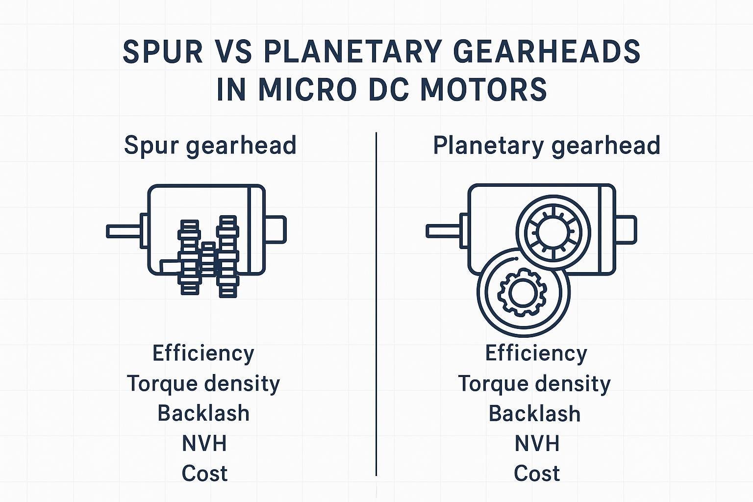
Think of these families as different trade-off bundles. If you start selection from “gearbox vs reducer” you won’t get far—most of your real decisions happen at the gear-family level (what many engineers shorthand as planetary vs helical vs worm gearbox decisions).
Planetary (epicyclic) reducers are typically chosen for high torque density in a coaxial package. Multiple planet gears share the load, which helps pack torque into a small diameter. INEED notes that load sharing is a core reason planetary stages deliver high torque density in a coaxial form factor in their planetary gearbox guide.
Helical reducers are generally selected when you want high efficiency, smoothness, and good noise performance in a parallel-shaft arrangement. They are a common baseline for industrial duty where packaging allows.
Bevel gearboxes are typically used when you need a right-angle layout but want to avoid some of the efficiency trade-offs of worm drives. Right-angle bevel stages are common when system layout forces a 90° turn.
Worm gear reducers are commonly used for right-angle drive with the added possibility of self-locking / non-backdrivable behavior, depending on lead angle and friction conditions. INEED’s explanation of the lead-angle/friction condition in their guide on worm gearboxes is a useful reminder: do not assume self-locking without checking the actual design and operating conditions.
Efficiency, backlash, torque density
These three parameters are often where “gear reducer vs gearbox” confusion becomes an engineering problem.
Efficiency (and why it shows up as heat)
Efficiency matters for two reasons: power loss and temperature rise.
For typical one-stage gear reducers, KHK describes very high transmission efficiency—on the order of 98–95% for one-stage reducers when properly designed/lubricated, in KHK’s overview of one-stage reducer efficiency (98–95%).
Worm gearboxes trade efficiency for layout and behavior. INEED states a broad worm gearbox efficiency range of 50% to 90% in their guide on how worm gearboxes work (INEED Motors), and explains why: sliding contact produces heat, which increases the importance of lubrication.
For planetary reducers, stage count is the practical “gotcha.” INEED highlights that higher ratios often mean more stages and more cumulative loss, and that loss becomes heat—affecting lubrication behavior and component temperatures—in their guide on how a planetary gearbox works (INEED Motors). The selection implication is simple: a ratio that looks fine on torque rating may still fail on thermal rise.
Pro Tip: Treat “efficiency” as an input to your thermal budget, not a marketing number. Ask for the efficiency at your operating point (speed/torque) and confirm whether it’s per-stage or overall.
Backlash vs torque density
Backlash is real, but it’s easy to misuse.
Backlash describes mechanical clearance and shows up as deadband on reversal.
But in many assemblies, the practical metric is lost motion under load, which includes backlash plus torsional wind-up (compliance) and flex in couplings/shafts.
If you need a reference point for expectations: ZIMM notes that bevel gearbox backlash “typically ranges within a few hundredths of a millimeter” in ZIMM’s note on bevel gearbox backlash (few hundredths of a mm). That’s not a universal spec, but it’s useful for calibrating “order of magnitude” when you’re deciding whether you need a precision product class.
Torque density is where planetary tends to win, particularly in coaxial packaging. That advantage can reduce envelope size, but it can also raise thermal density—again reinforcing that torque rating alone is not enough.
Inline vs right-angle, noise, maintenance
Layout constraints often decide the gearbox family before you ever calculate torque.
Inline / coaxial (planetary): compact and concentric with the motor axis. This is often the easiest to package in tight diameters.
Parallel shaft (helical): longer but can be efficient and quiet.
Right-angle (bevel or worm): helpful for packaging and routing, but you need to validate efficiency and heat.
Noise and maintenance follow from contact mechanics:
Helical meshes can be smoother and quieter than spur at comparable quality.
Worm drives can be quiet and compact, but sliding contact means lubrication quality and sealing matter for life and efficiency; INEED explicitly ties sliding contact to heat and the need for proper lubrication in their worm gearbox guide.
From a maintenance standpoint, don’t just ask “does it need maintenance?” Ask what the supplier expects you to control:
lubricant type and fill
seal life and orientation limits
permissible temperature range
expected life test conditions (load, speed, duty)
Selection and sizing guide
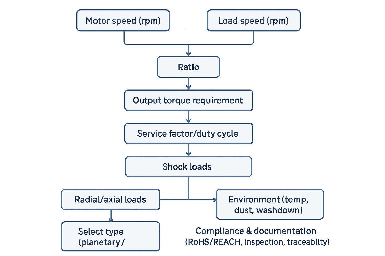
Step-by-step sizing
This is a practical flow you can apply regardless of whether the supplier calls the unit a “gearbox” or a “gear reducer.” The purpose is to translate application needs into a spec that survives EVT/DVT and procurement handoff.
1) Lock the speed requirement and compute ratio
Start with speeds. Ratio selection is usually framed as output speed relative to motor speed.
Required ratio (first pass):
i = n_in / n_out
Motion Control Tips walks through this selection logic and the consequences of ratio choice in Motion Control Tips’ gear ratio selection guide.
Engineering check: if you’re near a ratio boundary where stage count changes (for planetary), treat that as a design fork. A small ratio increase can mean an extra stage and a measurable thermal penalty.
2) Translate load to output torque (continuous and peak)
Define output torque as two numbers:
Continuous/RMS torque (thermal driver)
Peak torque (strength driver)
Be explicit about duty cycle and peak duration. If you only specify “max torque,” you invite a mismatch between what procurement buys and what the application actually does.
3) Apply service factor based on duty and shock
A gearbox that survives a lab test can still fail in the field if the duty cycle and shock loads were underestimated.
Use a service factor appropriate to:
duty cycle (continuous vs intermittent)
starts/stops and reversals
shock/impact loading
A practical gear-selection checklist is laid out in the gearbox selection checklist of must-have specs (WC Branham PDF), including the application questions that drive these factors.
⚠️ Warning: If your application has frequent reversals, don’t treat backlash as the only precision parameter. Lost motion under load is a combination of backlash, stiffness/compliance, and the rest of the drivetrain.
4) Validate efficiency at the operating point and close the thermal loop
At this point, many selections go wrong because “efficiency” is assumed rather than verified.
Ask for overall efficiency at your speed/torque, not a generic catalog number.
Convert efficiency to heat loss and check whether your enclosure can reject that heat.
This is especially important for:
high ratios (often multi-stage)
worm drives (wide efficiency range)
small housings in sealed devices
5) Confirm backlash/lost motion requirements (at load)
If you’re building positioning systems (robotics joints, lab automation, dosing/valves), define the acceptance test:
backlash measurement method
load during measurement
temperature range
whether “lost motion” or “repeatability” is the real KPI
If procurement only receives “low backlash,” you will not get consistent outcomes.
6) Check mechanical interfaces and shaft loads
Before finalizing, confirm:
mounting orientation constraints
radial and axial loads on the output shaft
overhung load location (e.g., pulley or gear position)
coupling misalignment tolerance
These are common late-stage redesign drivers because they’re not visible in a single torque rating.
7) Choose the architecture (planetary / helical-bevel / worm)
Use the earlier trade-offs, then validate with your actual load case:
Planetary: torque density + coaxial packaging; verify stage count losses/heat and the stiffness/backlash class you need.
Helical / bevel: strong baseline for efficiency and smoothness; bevel when right-angle is required.
Worm: right-angle packaging and possible self-locking behavior; verify efficiency and thermal rise; confirm whether backdriving is truly prevented in your use conditions.
8) Use engineering support to compress iteration cycles
This is where a supplier can materially reduce time-to-market—not by “better marketing,” but by faster iteration and clearer documentation.
If you’re working with INEED Motors, their process is oriented toward fast engineering turnaround and customization. For example, INEED states “All requests will be replied to in 8 hours,” and describes a multi-stage quality inspection approach as well as RoHS/REACH alignment on their company page.
In practical terms, that means you can often shorten your selection loop by submitting:
motor speed/voltage constraints
load speed/torque profile
duty cycle and thermal limits
packaging envelope and mounting orientation
backlash/noise requirements
documentation/compliance needs (RoHS/REACH, traceability, inspection reports)
…and asking for a proposed reducer family, ratio, and validation approach.
Gear reducer vs gearbox: quick comparison table
Use this as a procurement-friendly summary. The intent is to prevent miscommunication (e.g., buying a “gearbox” that wasn’t designed for reduction duty, or specifying a “reducer” when the real requirement is a direction/layout change).
Dimension | Gear reducer | Gearbox |
|---|---|---|
Primary function | Reduce speed and multiply torque at a defined ratio | Transmit power and change speed and/or direction (reduction, increase, or direction change) |
Structure / architecture | Typically specified around ratio + torque capacity; often discussed as a reducer stage set (may be integrated with motor) | Umbrella category that includes reducers plus right-angle and direction-changing architectures (bevel, worm, etc.) |
Precision (how it’s specified) | Commonly controlled via backlash / lost motion class, torsional stiffness, and stage count; must be defined at load and temperature | Same precision parameters apply, but specs often broaden to include shaft orientation, mounting layout, and interface tolerances |
Efficiency focus | Efficiency is evaluated as overall reduction efficiency at the operating point; multi-stage losses compound and turn into heat | Efficiency depends heavily on architecture (parallel/inline/right-angle) and intent (reduction vs direction change); don’t assume a single value |
Cost (relative + what drives it) | Relative cost: Low–High depending on ratio/stage count and precision class. Main drivers: ratio, backlash class, materials/heat treatment, bearings, and test requirements | Relative cost: Low–High depending on architecture and precision. Main drivers: right-angle requirements, housing/interfaces, shaft/bearing design, sealing/lubrication system, and validation scope |
Typical application scenarios | When your requirement statement starts with “reduce X rpm to Y rpm” and you need predictable torque multiplication (actuators, conveyors, dosing, compact motor+reducer assemblies) | When you need layout change, power transmission between shafts, or broader motion packaging constraints (right-angle routing, parallel-shaft transmission, mixed requirements) |
Decision matrix
Use this matrix as a first-pass decision tool. You still need to validate against your operating point.
Criterion | Planetary | Helical / Bevel | Worm |
|---|---|---|---|
Torque density / packaging | Strong in coaxial envelope | Moderate; often longer | Strong for right-angle compactness |
Efficiency sensitivity | Stage count matters; losses compound | Typically high in well-designed gear stages | Broad range; validate at operating point |
Backlash / precision options | Wide range incl. low-backlash classes | Depends on design class | Often not chosen for precision reversals |
Right-angle layout | Not inherent | Bevel fits naturally | Inherent right-angle |
Non-backdrivable / self-locking | Not typical | Not typical | Possible depending on design/conditions |
Noise | Depends on gear type/material and speed | Often good with helical meshes | Can be quiet; heat/lube matter |
Maintenance considerations | Lube + thermal management at high ratio | Standard gearing practices | Lube and sealing are first-class |
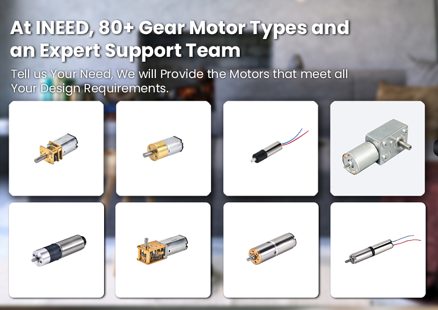
If you want a deeper overview of small motor gearbox families and where each fits, INEED’s roundup is a useful internal reference: motor gearbox types and applications.
Compliance & documentation
For OEM programs (especially in EU markets), documentation is a selection parameter—not an afterthought.
At minimum, treat these as part of your gearbox/reducer “definition of done”:
RoHS compliance declaration (restricted substances in homogeneous materials)
REACH SVHC disclosure (as required by your program)
Inspection and test records for key characteristics (e.g., torque, speed, noise where applicable)
Traceability expectations (lot/date codes, incoming material controls)
Change control expectations (how you’ll be notified of material or process changes)
If you’re qualifying a supplier, ask for a short, program-specific “doc pack” checklist rather than a generic promise. INEED describes their inspection flow and their RoHS/REACH alignment on the company page linked earlier.
Conclusion
Use the terms precisely to avoid mis-purchasing:
Gearbox is the broad class (transmit power, potentially change speed and/or direction).
Gear reducer / speed reducer is a gearbox applied specifically to reduce speed and multiply torque.
Selection is rarely decided by the label. It’s decided by the criteria that change sizing and life: efficiency and heat at the operating point, stage count (especially for high ratios), backlash vs lost motion under load, layout constraints (inline vs right-angle), and lubrication/maintenance realities.
If you follow the sizing flow—speed → ratio → torque (RMS and peak) → service factor → thermal → shaft loads → precision/noise → documentation—you’ll turn a vague “gearbox vs reducer” purchase into a defensible engineering spec that procurement can execute without surprises—and make the gear reducer vs gearbox decision much easier to document and audit.
If you’d like, share your speed/torque profile, envelope limits, and documentation requirements, and an engineer can sanity-check architecture, ratio staging, and compliance readiness before you cut a PO. For supplier-side documentation expectations and compliance positioning, see INEED Motors quality control and RoHS/REACH compliance.
FAQ
What efficiency should I expect from a planetary vs worm gearbox?
Expect planetary gear reducers to be relatively efficient per stage, but remember that overall efficiency drops as stage count increases (higher ratios often mean more stages and more cumulative losses). For worm gearboxes, efficiency can vary widely and is highly dependent on design details and operating conditions—so you should validate efficiency at your actual speed/torque point and treat any loss as heat that must be dissipated.
How do I choose a gear reducer ratio?
Start with your target output speed and motor speed, then do a first-pass ratio calculation: i = n_in / n_out. After that, verify you’re not unintentionally crossing a stage-count boundary (common in higher planetary ratios), and sanity-check that the ratio you picked still meets torque (RMS and peak) and thermal limits at the real duty cycle.
How much backlash is acceptable?
It depends on whether your system is sensitive to reversals and positioning. For simple continuous rotation applications, moderate backlash may be fine; for positioning or frequent reversals, define the requirement as lost motion under load (not just catalog backlash), including the measurement load, temperature, and the rest of the drivetrain stiffness. If your application is precision-sensitive, ask for a backlash/lost-motion test method that matches your use case.