If you searched for dc motor components, parts of a DC motor with diagram, or dc motor parts and functions, you’re usually trying to do one of two things: understand how a DC motor works, or identify which part is causing a performance issue (noise, heat, low torque, poor efficiency).
In this guide, you’ll learn the most important dc motor parts (and the broader set of electric motor parts) including the stator, rotor, windings, bearings, shaft, air gap, commutator, brushes, and housing. We’ll also cover how these components differ between brushed DC motors and BLDC motors.
Electric motors are a major electricity consumer worldwide. The International Energy Agency (IEA) estimates motors account for about 45% of global electricity use, largely in industrial systems.
By the end, you’ll have a clear mental model of the parts of a DC motor, what each part does, what it’s commonly made from, and how the parts work together to create torque and speed.
Key Takeaways
The main dc motor parts include the stator, rotor (armature), windings, bearings, shaft, air gap, and housing—core dc motor components that convert electrical energy into torque and speed.
In a brushed DC motor, the commutator and brushes are essential parts of a DC motor because they switch current mechanically to keep torque in one direction.
In a BLDC motor, commutation is electronic, so the motor’s performance depends heavily on the stator windings, rotor magnets, the air gap, and the external driver (and sometimes sensors).
Bearing quality, shaft alignment, and air-gap control strongly influence efficiency, noise, and service life for both brushed DC and BLDC designs.
Understanding dc motor parts and functions helps you troubleshoot faster and choose a motor architecture that fits your load, speed, lifetime, and control requirements.
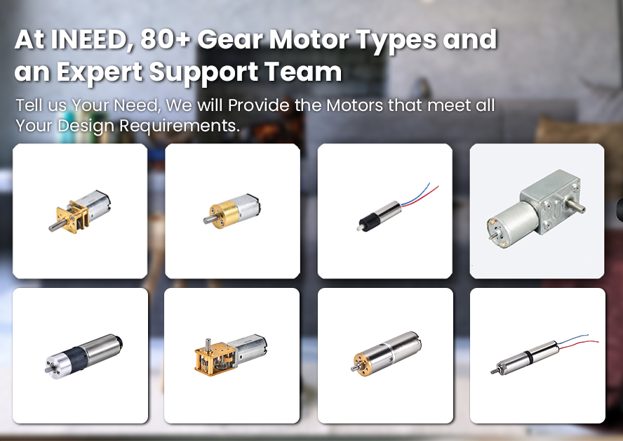
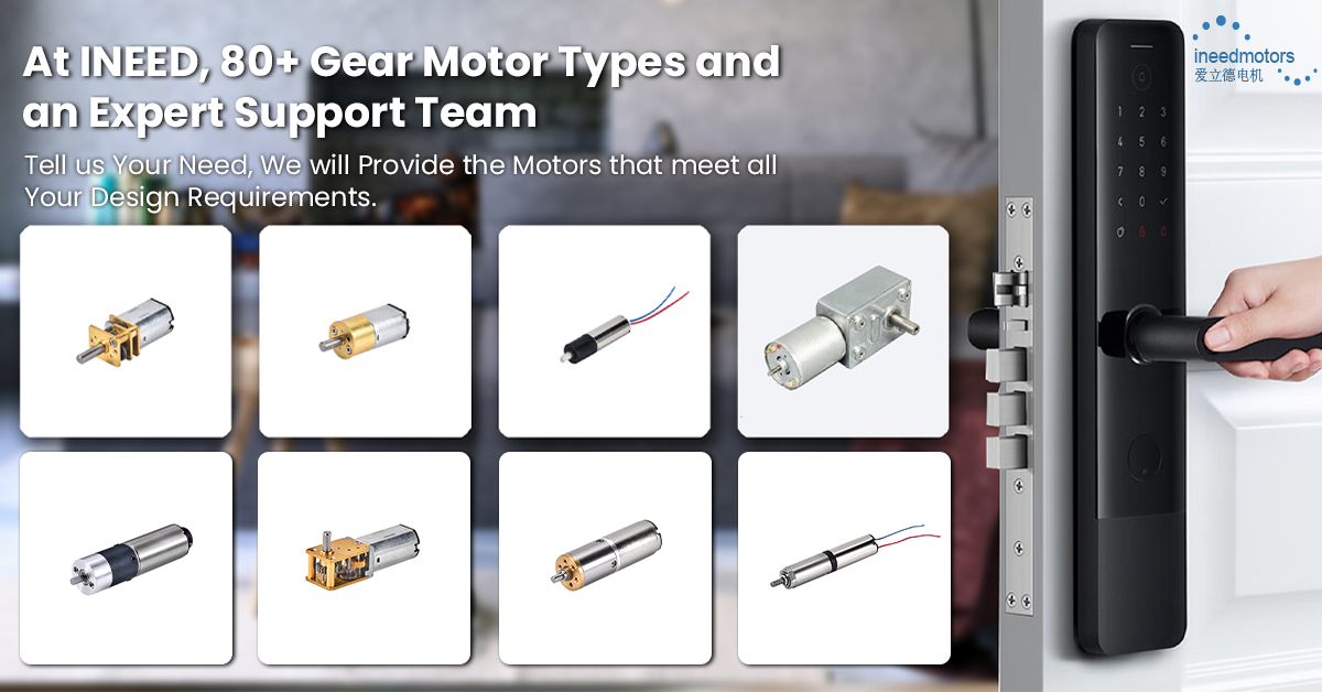
If you’re comparing miniature solutions for products, you can also reference INEED Motors’ overview of small gear motor options and how different motor/gearbox combinations change torque and speed.
Electric Motor Parts Overview
Main Components of an Electric Motor
When you open a motor, you see many parts. Each part has a job to do. All the parts work together to make movement from electricity. Here are the main parts you will find in most motors:
Stator: This part does not move. It makes a magnetic field.
Rotor: This part spins inside the stator. It changes electricity into movement.
Windings: These wires carry electricity and help make the magnetic field.
Bearings: These hold up the rotor and let it spin easily.
Shaft: This connects to the rotor and brings the spinning force out.
Air gap: This is a small space between the stator and rotor.
Commutator: This part helps switch the direction of electricity in some motors.
Armature: This holds the windings and spins with the rotor.
Field magnets: These make a strong magnetic field.
Power source: This gives the motor electricity.
Enclosures: These keep the inside parts safe from dust and harm.
Different motors use these parts in their own ways. DC motors use direct current. They have armature windings and field windings. AC motors use alternating current. They can be single-phase or three-phase. Some motors, like stepper motors and servomotors, have special shapes for special jobs.
DC Motor Components Explained: What Matters in Real Designs
Many pages list generic electric motor parts, but engineers usually care about what changes performance in DC motor components: torque density, speed, efficiency, lifetime, and controllability. Below are the component-level details that most directly affect those outcomes.
Commutator and Brushes: only in Brushed DC motors
In a brushed DC motor, the commutator and carbon brushes act like a mechanical “switch.” They reverse the current in the armature coils as the rotor turns, which keeps the torque direction consistent.
What to know:
Material and surface finish of the commutator influence brush wear, arcing, and electrical noise.
Brush grade (carbon/graphite vs copper-graphite) is selected based on current density, speed, and expected life.
If you see black dust, sparking, or intermittent torque, the brush-commutator system is often a prime suspect.
Stator and rotor design: where torque really comes from
Whether it’s brushed or BLDC, torque depends on how effectively the stator field and rotor field couple across the air gap.
Key design levers include:
Magnet type (ferrite vs NdFeB) affects flux density and therefore torque density.
Lamination quality and thickness affect iron losses at speed (especially important for high-RPM motors).
Winding fill factor (how much copper fits in the slot) affects resistance, heating, and efficiency.
Bearings and the shaft: small parts, big reliability impact
For miniature and high-speed motors, bearing choice can decide real-world lifetime.
Sintered bronze bushings are compact and cost-effective for moderate speeds and loads.
Ball bearings typically reduce friction at higher speeds and support higher radial loads.
Shaft material and hardness help prevent wear at coupling points (gears, pulleys, press fits).
Sensors and electronics: critical for BLDC
A BLDC motor eliminates mechanical commutation, but it typically shifts complexity into the drive system.
Common options:
Hall sensors for robust commutation in many industrial designs.
Encoders when you need precise speed/position control.
Sensorless control in some applications, where back-EMF estimation replaces physical sensors.
Quick troubleshooting map: symptom → likely component
Symptom | Common component causes |
|---|---|
Sparking / EMI / black dust | Brushes, commutator, brush springs |
Grinding noise / vibration | Bearings, shaft alignment, rotor imbalance |
Low torque at rated voltage | Magnets demagnetized, winding damage, air gap issues |
Overheating | Winding resistance too high, poor heat path through housing, overload |
Poor speed stability (BLDC) | Sensor/encoder, controller tuning, phase wiring |
These are the most practical “why it behaves this way” links between dc motor parts and functions and performance in a product.
Motor Type | Power Source | Main Components Description | Typical Applications |
|---|---|---|---|
DC Motors | Direct Current (DC) | Stator: permanent magnets or electromagnets; Armature and field windings arranged differently (series/shunt) | Toys, tools, appliances |
AC Motors | Alternating Current | Single-phase: two wires (hot and neutral), up to 3kW; Three-phase: three alternating currents, up to 300kW | Single-phase: homes, small appliances; Three-phase: industrial machinery |
Special Purpose | Varies | Unique designs like stepper motors (discrete steps), servomotors (fast response), reluctance, linear motors | Robotics, signal generators, heavy goods handling |
How Electric Motors Work
You may wonder how these parts work together. The stator makes a moving magnetic field when electricity goes through its windings. The rotor sits inside the stator. The magnetic field from the stator makes the rotor spin. Bearings help the rotor turn without problems. The shaft connects to the rotor and brings the spinning power to what you want to move.
Note: The enclosure keeps all the parts in place and helps cool the motor.
Each part helps the motor work well. The stator and rotor work together to turn electricity into movement. The bearings and shaft help the movement stay smooth. The enclosure keeps the motor safe and helps it last longer. When you know about these parts, you can understand how a motor works and why each part is important.
Stator and Rotor
Parts of a DC Motor With Diagram
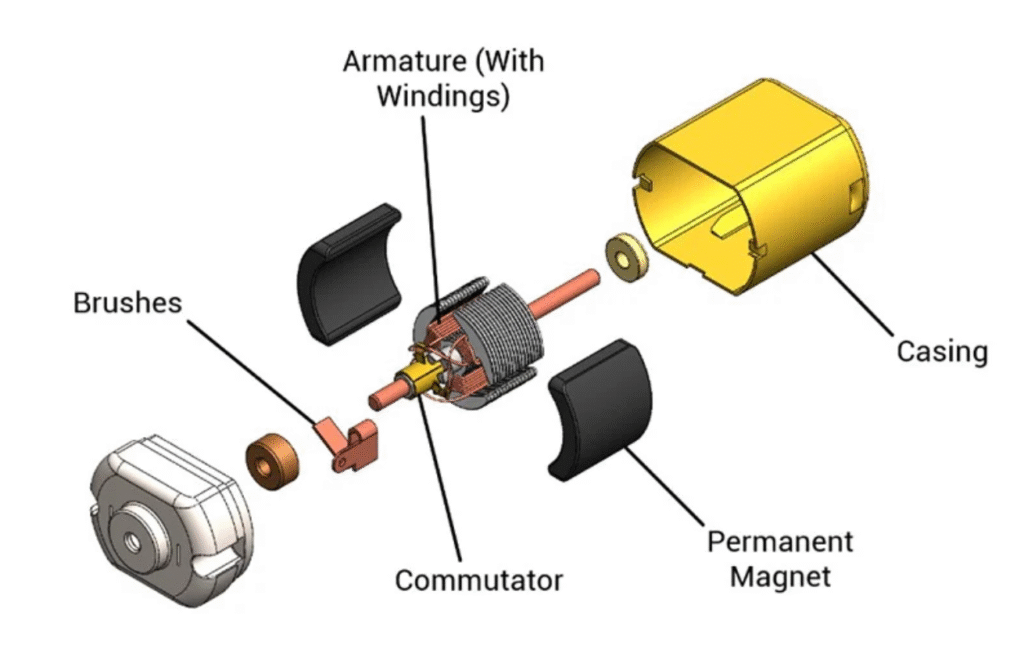
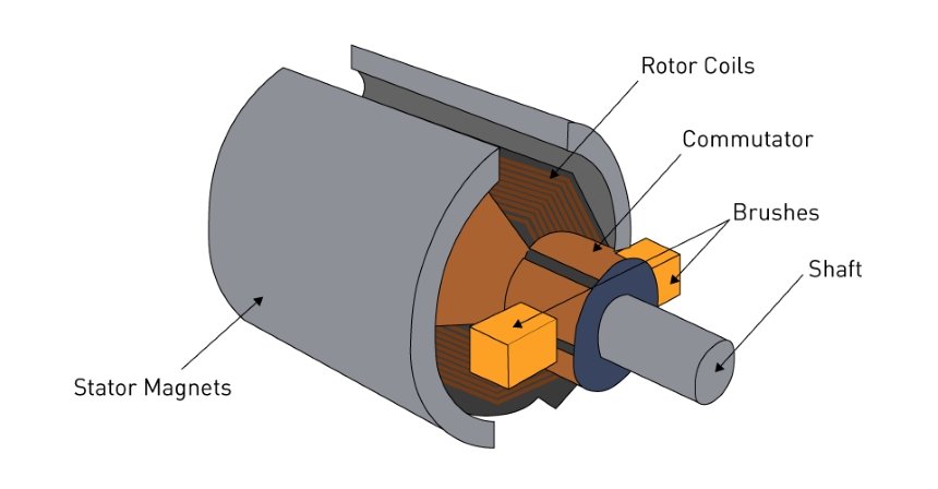
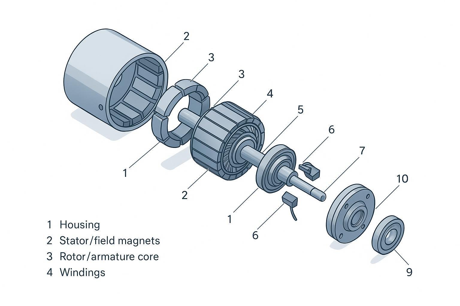
Below are two labeled, isometric exploded diagrams to help you visualize the parts of a DC motor with diagram style—one for a brushed DC motor and one for a BLDC motor. The numbered callouts map to the component legend tables.
Brushed DC motor component legend (numbers → name, function, typical materials)
No. | Part name | Function in a DC motor | Typical materials |
|---|---|---|---|
1 | Housing / frame | Protects internal components; supports alignment; provides heat path | Steel, aluminum, engineered plastics |
2 | Stator / field magnets | Creates stationary magnetic field that interacts with armature field | Ferrite magnets, NdFeB magnets; sometimes laminated steel with field windings |
3 | Rotor / armature core | Rotating magnetic circuit; carries armature windings and produces torque | Laminated electrical steel; sometimes cobalt steel |
4 | Armature windings | Carry current to create armature magnetic field | Enameled copper wire; sometimes aluminum (cost-sensitive) |
5 | Commutator | Mechanical switching that reverses armature current for continuous torque | Copper segments with mica insulation |
6 | Carbon brushes | Transfer current from stationary circuit to commutator; enable commutation | Carbon/graphite, copper-graphite |
7 | Shaft | Transfers torque to gearbox/load; sets rotor centerline | Alloy steel, stainless steel |
8 | Bearings | Reduce friction; support shaft radially/axially | Sintered bronze bushings; steel ball bearings |
9 | End cap / end bell | Holds bearings/brush holders; closes motor; maintains geometry | Steel, aluminum, engineered plastics |
10 | Air gap | Magnetic coupling space between stator and rotor (critical to efficiency/torque) | Designed clearance (not a material) |
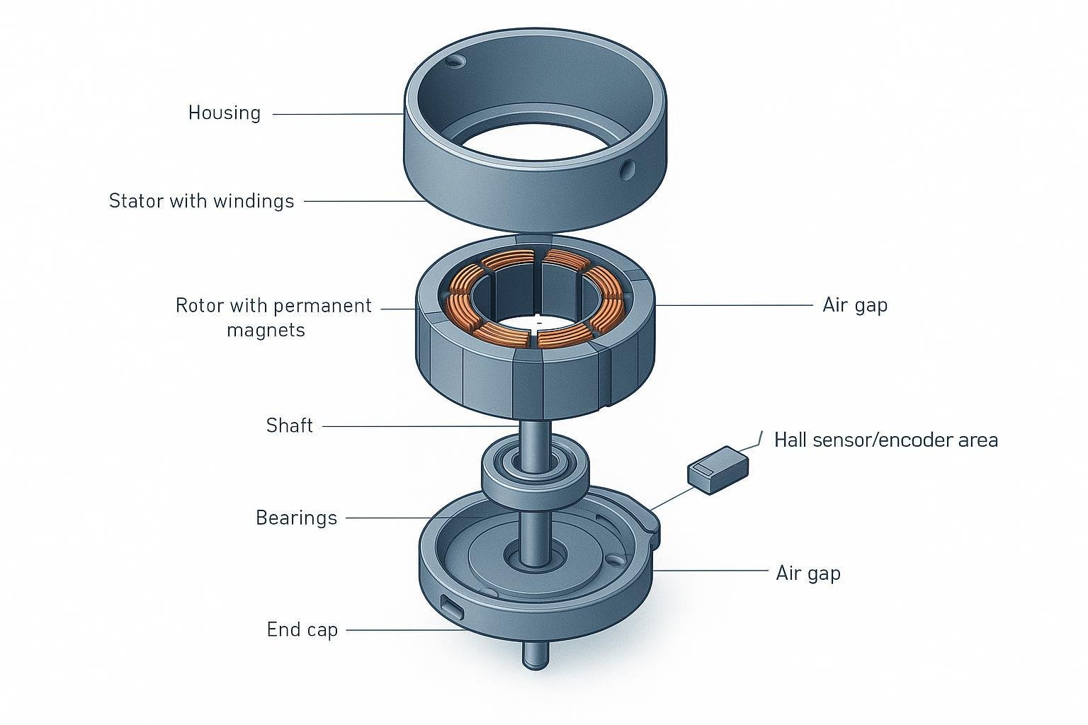
BLDC motor component legend (numbers → name, function, typical materials)
No. | Part name | Function in a BLDC motor | Typical materials |
|---|---|---|---|
1 | Housing / frame | Protection, alignment, and thermal path | Aluminum, steel |
2 | Stator core + slots | Magnetic circuit for stator windings; enables rotating field when driven | Laminated electrical steel |
3 | Stator windings | Create rotating magnetic field (electronic commutation) | Enameled copper wire |
4 | Rotor with permanent magnets | Provides rotor magnetic field; responds to stator rotating field | NdFeB magnets; rotor back iron in laminated steel |
5 | Shaft | Transfers torque to the load | Alloy steel, stainless steel |
6 | Bearings | Support shaft; reduce friction and noise | Steel ball bearings; sometimes fluid bearings in precision designs |
7 | End cap | Keeps geometry stable; supports bearing seats | Aluminum, steel |
8 | Position feedback area | Helps controller commutate (Hall sensors or encoder in many designs) | Hall ICs on PCB; optical/magnetic encoder parts |
9 | Air gap | Magnetic coupling space (tight control improves efficiency/torque) | Designed clearance (not a material) |
Brushed DC vs BLDC: what’s different in the parts?
Topic | Brushed DC motor | BLDC motor |
|---|---|---|
How current switches | Commutator + brushes mechanically switch current | Controller (ESC/driver) switches phases electronically |
Wear parts | Brushes/commutator wear; dust and arcing possible | No brushes; bearings usually become the primary wear item |
Efficiency & noise | More electrical/brush losses; more EMI/noise risk | Often higher efficiency; quieter electrical operation |
What you must add outside the motor | Simple DC supply (sometimes PWM driver) | Requires a BLDC driver/controller; often needs position feedback |
Stator Function
The stator is a very important part of an electric motor. It stays still and surrounds the spinning rotor. The stator’s main job is to make a magnetic field that moves. When electricity goes through the stator windings, the stator makes this field. This field pushes on the rotor and makes it turn. The stator core sits inside the stator frame. It helps guide and make the magnetic field stronger.
Manufacturers use different materials for the stator to make motors better. Here is a table that lists common stator materials and what they do:
Material | Core Losses | Magnetic Properties | Weight Reduction | Thermal Conductivity |
|---|---|---|---|---|
Traditional Silicon Steel | Moderate | Good | Low | Moderate |
Amorphous Steel | Low | Excellent | Moderate | High |
Nanocrystalline Alloys | Very Low | Superior | Moderate | High |
Composite Materials | N/A | Varies | High | Varies |
Most motors use silicon steel for the stator. It has good magnetic properties and does not waste too much energy. Newer materials like amorphous steel and nanocrystalline alloys help save more energy. They also make motors work better. Composite materials make the stator lighter. This is helpful for special uses.
The stator’s main job is to make a moving magnetic field. This field works with the rotor to make things move. Changing the current’s direction keeps the rotor spinning. This turns electrical energy into movement.
Rotor Function
The rotor sits inside the stator and spins when the motor is on. The rotor is the part that moves and makes the motor work. The rotor core holds the main magnetic parts. It helps the rotor react to the stator’s magnetic field. Most rotors use thin layers made from silicon or cobalt iron. These materials help the rotor work well and waste less energy.
The rotor can have a shaft, windings, and sometimes permanent magnets. The rotor connects to the shaft. The shaft carries the spinning force out of the motor. Some rotors use permanent magnets to make a steady magnetic field. Other rotors use coils that get power from the stator’s field.
The rotor lines up its magnetic poles with the stator’s field.
If the rotor has permanent magnets, they work with the stator’s field.
In induction motors, the stator’s field makes a current in the rotor. This current makes its own magnetic field.
The rotor core and its materials change how well the rotor spins and how much energy the motor uses.
Interaction Between Stator and Rotor
The stator and rotor working together make the motor run. When you turn on the motor, the stator makes a magnetic field. This field moves inside the stator. The rotor sits inside this moving field. The stator’s field pulls and pushes on the rotor. This makes the rotor spin. The spinning is used to power machines, fans, or tools.
The stator makes a magnetic field by sending current through its coils.
This field works with the rotor’s magnetic field, which comes from magnets or coils.
The force between the fields makes torque, which spins the rotor.
How fast and smooth the rotor spins depends on how the stator changes its field.
Lighter rotor materials help the rotor spin faster and use less energy.
You can see that the parts of an electric motor work together in a simple way. The stator and rotor are the main parts of the motor. The stator frame holds everything in place. The stator core and rotor core help guide the magnetic fields. When you know how these parts work together, you can see why electric motors are so useful every day.
Windings, Armature, and Field Magnets
Windings Role
Windings are very important in an electric motor. Every motor has different types of winding. These include stator winding, rotor winding, armature winding, and field winding. Each type does something special. The stator winding is in the part that does not move. It makes the main magnetic field. Rotor winding is on the part that spins. It helps make the motor turn. Armature winding is where most energy changes happen. Field winding makes the main magnetic field flux.
Here is a table that shows the main types of winding and what they do:
Type of Winding | Placement | Key Characteristics and Function | Typical Usage |
|---|---|---|---|
Stator Winding | Stationary part (stator) | Produces magnetic field; in DC motors, creates constant flux; in induction motors, produces rotating magnetic field | DC motors, induction motors |
Rotor Winding | Rotating part (rotor) | Wound on rotor core; in DC motors acts as armature winding; in synchronous motors excited by DC; develops torque | DC motors, synchronous motors, induction motors |
Armature Winding | Usually rotor or stator | Main winding where electromagnetic torque is developed; induces emf and creates torque | Electric motors generally |
Field Winding | Stator or rotor | Creates main magnetic field flux; excited by DC or AC depending on motor type | DC motors (stator), synchronous motors (rotor), induction motors (stator) |
Windings make the magnetic fields that help the motor work. When electricity goes through the windings, they make a magnetic field. This field works with the rotor and makes it spin. The changing magnetic field from the rotor and the stator winding lets the motor run.
Armature Purpose
The armature is another important part of the motor. It is the part that changes electrical energy into movement. The armature is usually on the rotor and holds the windings. Here is what the armature does:
The armature spins and holds the windings where current goes.
Current in the armature winding makes a magnetic field.
This field works with the stator’s magnetic field.
The force between these fields makes the armature turn.
The spinning armature changes electrical energy into movement.
More current in the armature means more torque.
The commutator helps switch the current in the armature winding so the motor keeps turning.
The armature is where most of the energy changes in the motor.
Field Magnets Effect
Field magnets are also very important in an electric motor. You can find them in the stator as permanent magnets or electromagnets. Field magnets make the main magnetic field in the motor. This field works with the field made by the windings in the rotor. The push and pull between these fields make the rotor turn. Stronger field magnets make the motor work better and stronger. Permanent magnets, like neodymium, help motors stay small and need less care. Electromagnets let you change how strong the magnetic field is. Field magnets are a big part of how well the motor works and how much energy it uses.
Bearings, Shaft, and Air Gap
Bearings Function
Bearings play a key role in every electric motor. You find them supporting the shaft and helping it spin smoothly. Bearings reduce friction by allowing the shaft to roll instead of slide. This rolling motion cuts down on heat and wear inside the electric motor. Bearings also support the weight and forces that happen when the shaft turns. They keep the shaft in the right place, so it does not wobble or move out of line. When you have good bearings, your electric motor runs quietly and lasts longer.
Bearings reduce friction between moving parts.
They support both the weight and the spinning forces of the shaft.
Bearings keep the shaft aligned for smooth and efficient operation.
They help prevent early wear and damage inside the electric motor.
Tip: If you hear grinding or feel vibration from your electric motor, check the bearings first.
Shaft Role
The shaft is the part that brings the spinning power out of the electric motor. You see the shaft sticking out from the center of the motor. It connects to things like gears, pulleys, or fans. The shaft takes the turning force from the rotor and delivers it to whatever you want to move. The shaft must stay strong and straight, even when the electric motor works hard. It supports the rotor and keeps everything balanced. The design and material of the shaft matter a lot. A well-made shaft helps your electric motor work better and last longer.
The shaft connects the rotor to outside equipment.
It delivers torque and speed from the electric motor to your machines.
The shaft supports the rotor and keeps it stable.
It must handle both sideways and end-to-end forces.
The motor shaft must fit tightly and stay aligned to avoid energy loss.
Importance of Air Gap
The air gap is the small space between the stator and the rotor in an electric motor. This gap may look tiny, but it has a big effect on how well your motor works. If the air gap is too large, the electric motor loses power and needs more energy to run. If the gap is too small, the rotor and stator might touch, which can cause damage. A well-sized air gap helps the electric motor run quietly, with good torque and less noise. Most small motors use an air gap between 0.25 and 1.5 millimeters. Medium motors use a gap up to 2 millimeters. The right air gap keeps your electric motor efficient and reliable.
A large air gap lowers efficiency and increases energy use.
A very small air gap can cause noise and lower starting power.
The right air gap keeps the electric motor running smoothly and safely.
Commutator, Power Source, and Enclosures
Commutator Purpose
The commutator is a very important part in a DC motor. You will find it connected to the rotor. Its main job is to help the motor spin the same way every time. The commutator does this by changing the direction of current in the armature coils at the right moment. This lets the motor make steady turning force. Here is what the commutator does:
It changes the current in the armature coils so the torque keeps going the same way.
It keeps the electric connection between the spinning armature and the brushes that do not move.
It stops sparks at the brushes, which helps them last longer and keeps the motor safe.
It uses things like interpoles and special brush setups to make switching smooth and stop arcing.
It needs regular care, like cleaning and checking for damage, to work well and keep other parts safe.
If you take care of the commutator, your motor will run better and last longer.
Power Source Role
The power source is another important part of an electric motor. It gives the motor the energy it needs to work. You can use a battery, a wall plug, or a generator as your power source. The kind of power source you need depends on your motor. DC motors need direct current, but AC motors use alternating current. The power source must give the right voltage and current for the motor. If you use the right power source, your motor will work safely and well. If you use the wrong one, you might break the motor or make it stop working.
Enclosures and Protection
Enclosures keep electric motor parts safe from dust, water, chemicals, and bumps. You see them as the outside shell or case around the motor. The enclosure keeps bad things out and helps with air and heat flow. This helps your motor last longer and work better. Enclosures also keep you safe by stopping you from touching moving or live parts. Some enclosures are made for hard places, like outside or in factories. Picking the right enclosure helps you avoid repairs and keeps your motor in good shape.
Tip: Always look at the enclosure for cracks or damage. A strong enclosure keeps your electric motor parts safe and clean.
How Electric Motor Parts Work Together
Energy Conversion Process
When you look inside an electric motor, you see many parts working together. Each part has a job that helps change electricity into movement. First, you give power to the motor. The power source sends electricity to the windings. These windings are on the stator or rotor, depending on the motor type.
The windings make a magnetic field when electricity flows through them. This field works with the field magnets or the stator’s magnetic field. The stator does not move, but it makes a moving magnetic field. The rotor sits inside the stator and spins when the magnetic field pushes and pulls on it. The rotor follows the changing magnetic field, so it spins. This spinning makes torque, which is the force that turns the shaft.
Bearings hold up the shaft and help it spin smoothly. The shaft takes the spinning force out of the motor. You can use this force to run things like fans or pumps. The air gap between the stator and rotor keeps them from touching but lets the magnetic field work well. The commutator in some motors switches the current’s direction. This keeps the rotor spinning the same way. The enclosure covers all the parts and helps keep the motor cool.
You see electric motors in many places. They are in cars, home appliances, and factories. Electric motors also work in robots, elevators, and toys. You can use them almost anywhere you need something to move. The way electric motors change energy makes them useful for many jobs.
Tip: If you want your motor to work better, keep the air gap just right and use good bearings. This helps your motor waste less energy and last longer.
Summary of Component Interaction
You can think of an electric motor as a team where every part is important. The stator and rotor work together to make movement. The windings and field magnets make the magnetic fields that move the rotor. The bearings and shaft help the rotor spin and send power to your machines. The air gap lets the magnetic field work without the parts touching.
The commutator and brushes in some motors keep the current going the right way. The enclosure keeps dust and water out, so the motor stays safe. When you put all these parts together, you get a machine that changes electricity into movement. You can see how well a motor works by looking at things like speed, torque, and efficiency.
If you want your motor to work its best, you must take care of every part. Clean windings, smooth bearings, and a strong enclosure help your motor run better. You get more efficiency and a longer life from your motor. You also get steady power for all your needs.
Here is a quick look at how the main parts work together in electric motors:
Part | What It Does | Why It Matters for Electric Motors |
|---|---|---|
Stator | Makes the main magnetic field | Starts the energy conversion process |
Rotor | Spins inside the stator | Turns electrical energy into movement |
Windings | Carry current and create magnetic fields | Drive the rotor and control speed |
Bearings | Support the shaft and reduce friction | Keep the motor running smoothly |
Shaft | Delivers spinning force to machines | Transfers power to your application |
Air Gap | Separates stator and rotor | Affects efficiency and performance |
Commutator | Switches current direction (in some motors) | Keeps the rotor spinning correctly |
Enclosure | Protects all parts | Increases motor life and safety |
You can see that electric motors need every part to work together. If one part stops working, the whole motor can stop or lose power. You should check each part if you want your electric motors to keep running well.
Note: Electric motors give you strong and steady power for many jobs. You get better performance and high efficiency when you take care of every part.
You now know the main parts of an electric motor and what they do. The stator, rotor, windings, bearings, shaft, air gap, commutator, armature, field magnets, power source, and enclosures all have their own jobs. These parts work together to change electricity into movement. Electric motors are used in many things, like home tools and machines in factories. If you know the parts, you can see how electric motors help and where they are used.
Common problems include:
Overheating can hurt winding insulation and cause shorts.
Too much electricity can damage inside parts.
Worn bearings make noise and can break the motor.
Bad insulation can cause short circuits.
Vibration can harm bearings and other parts.
If you know these basics, you can find problems early and pick the right motor for your needs. You get more out of your motor if you take care of it and use it for the right job. Electric motors are important because they help us every day in many ways.
FAQ
What are the main parts of a DC motor?
The main parts of a DC motor include the stator (field magnets or field windings), rotor (armature core), windings, shaft, bearings, and housing. In a brushed DC motor, you also have a commutator and carbon brushes. In a BLDC motor, commutation is electronic, so you typically add a controller and sometimes Hall sensors or an encoder.
What is the difference between brushed DC motor components and BLDC motor components?
The biggest difference is commutation. Brushed DC motors use brushes + commutator to switch current mechanically, which introduces wear and electrical noise. BLDC motors use electronic commutation through a driver/controller and often rely on position feedback (Hall sensors/encoder or sensorless estimation). Many other dc motor components—stator, rotor, bearings, shaft, and air gap—exist in both.
What does the commutator do in a DC motor?
In a brushed DC motor, the commutator reverses current direction in the armature windings at the right time so torque keeps acting in the same rotational direction. It also provides the rotating electrical contact surface for the brushes.
Why is the air gap so important in DC motor parts and functions?
The air gap strongly affects magnetic coupling. Too large, and the motor produces less torque and wastes more energy. Too small, and you risk rotor-stator contact, noise, and rapid wear. Tight air-gap control is especially important for small, high-efficiency motor designs.
What materials are DC motor parts usually made from?
Typical materials include laminated electrical steel for stator/rotor cores, copper for windings, ferrite or NdFeB for magnets, copper/mica for commutators, carbon/graphite for brushes, steel for shafts, and bronze bushings or steel ball bearings for bearing elements. Exact choices depend on speed, load, efficiency targets, and cost.
What should you check first if a DC motor makes noise?
Start with bearings and shaft alignment because they commonly cause grinding, rattling, or vibration. If it’s a brushed DC motor, also inspect the brushes and commutator for wear, contamination, or sparking.
How do I choose between brushed DC and BLDC for my product?
Choose brushed DC for simpler control and lower upfront electronics complexity when wear life and EMI are manageable. Choose BLDC when you want higher efficiency, longer service life (no brushes), and better high-speed performance—assuming you can add the right driver and, if needed, sensing.