Introduction
A DC motor wiring diagram is only useful if it tells you exactly what to connect, in what orientation, and what electrical behavior the system will produce when firmware starts switching. In EVT/DVT, the diagram is also a risk-control document: it should make it hard to miswire a harness, easy to probe expected voltages, and explicit about protection parts and grounding.
At minimum, a diagram that’s ready for implementation should cover power (rails, return path, decoupling), control (PWM/direction/brake inputs), feedback (Halls/encoders), protection (fuse/TVS/reverse-polarity), and EMC choices (shielding, grounding, cable routing). Monolithic Power Systems’ overview of motor control circuit building blocks is a good high-level reference for how these blocks fit together.
This guide covers two common families:
Brushed DC motors (BDC): two-lead polarity, brushed DC motor wiring basics, H-bridge control, PWM and braking behavior.
Brushless DC motors (BLDC): BLDC wiring diagram essentials—three-phase wiring (U/V/W), direction, commutation basics, and safe switching.
It also includes the most common harness variants you’ll see in products:
3-wire brushless motor wiring (fan-style BLDC): power, ground, and a speed control (PWM or analog) lead.
4 wire brushless motor diagram (fan-style BLDC): adds a tach/sense output for closed-loop speed monitoring.
BLDC + Hall leads (5/6 wires+): three power phases plus Hall sensor power/ground and signals.
3-phase ESC wiring: battery input to ESC, three phase outputs to the motor, and a control input (typically RC PWM).
It’s written for OEM engineering teams validating prototypes and building harnesses for EVT/DVT and early DVT. Use it like a checklist: read each section, compare against your motor and driver datasheets, then verify with a DMM and scope before you run full-load tests.
Brushed DC wiring basics in a DC motor wiring diagram
Two-lead polarity and direction
A brushed DC motor has two power leads to the armature. This is the core of brushed DC motor wiring. In the simplest case:
Apply +V to one lead and GND to the other → the motor spins in one direction.
Swap polarity → the motor spins the other way.
What matters for wiring diagrams is not just “swap the wires,” but where the polarity is defined. Your diagram should clearly label:
The motor terminals (or connector pins)
The expected direction (CW/CCW) as viewed from a defined side (shaft end vs. rear end)
The measurement reference (e.g., “CW when viewed from shaft end at +V on M+”)
Pro Tip: Put the “view direction” note next to the motor symbol, not buried in a footnote. Direction ambiguity is a common EVT/DVT time sink.
Typical supply and connectors
For brushed DC in product builds, your wiring diagram should explicitly show:
Supply rails: VBAT/VIN and GND (or +24V/0V, etc.), with expected voltage range.
Motor connector: keyed connector designation (Jx), pin numbers, and wire gauge/insulation requirements.
Current path: where the high current flows (battery → protection → driver → motor → return). This helps layout and harness teams avoid routing sensitive signals alongside the highest di/dt paths.
If you expect field service or factory test, add test points for VBAT and driver output nodes so the build can be validated without back-probing connectors.
Wire color conventions caveat
Wire colors help humans, but they are not an electrical standard across suppliers or harness assemblies. A good wiring diagram treats color as secondary:
Identify each wire by net name and connector pin first.
Then optionally add color as a manufacturing aid.
If you inherit a motor with color-coded leads, confirm the mapping with the datasheet or a quick bench test rather than trusting color alone.
H-bridge wiring: control, PWM, and braking
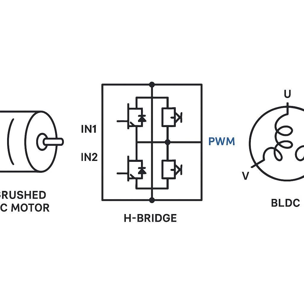
An H-bridge lets you reverse a brushed motor’s polarity electronically and apply PWM for speed/torque control. Wiring diagrams for H-bridges fail when they don’t communicate states: what happens to the motor terminals when the controller commands forward, reverse, coast, or brake.
IN1/IN2 vs PH/EN interfaces
Two common digital control interfaces are:
IN1/IN2 (two-input “PWM interface”)
PH/EN (phase + enable)
Texas Instruments summarizes the trade-offs in its PH/EN vs PWM interface FAQ (2020): PH/EN can be simpler (one PWM), while IN1/IN2 can offer more flexible output states (including a Hi-Z/coast state on many drivers).
In a wiring diagram, show not just the pins, but the logic assumptions:
Which pins are driven by PWM-capable MCU outputs
What the default state is on reset (pull-downs/pull-ups)
Whether the driver supports Hi-Z outputs or enforces a particular decay/brake behavior
PWM placement and decay behavior
PWM isn’t just “on/off fast.” Where the bridge places PWM (which transistor(s) chop) affects current recirculation and therefore torque ripple, heating, and audible noise.
A practical wiring diagram should at least note:
The PWM input pin(s) and expected frequency range from the motor driver datasheet
Whether the system intends coast (Hi-Z) during PWM off-time or recirculation (slow decay)
Any current sensing requirements (e.g., shunt placement) that depend on recirculation path
If you need a baseline for wiring-centric decisions, start with a driver vendor’s layout and decoupling guidance. TI’s “Best Practices for Board Layout of Motor Drivers” (SLVA959) is a useful reference because many “PWM problems” are actually loop inductance and return-path problems.
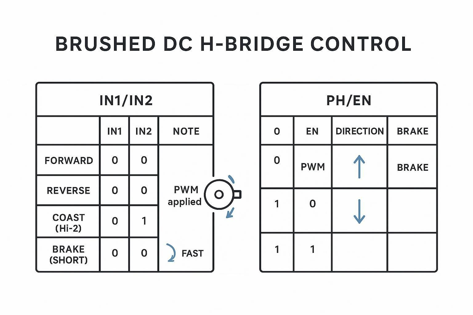
Coast, brake, and dynamic braking limits
The three behaviors to distinguish:
Coast: motor terminals effectively open (or not actively driven), motor slows due to friction and load.
Brake (short-brake): motor terminals are shorted together through the bridge → fast deceleration, current spikes depend on speed and motor constants.
Dynamic braking into supply: some systems can return energy to the supply or clamp it; often limited by driver topology and protection components.
Two wiring implications engineers often miss:
Braking current has to go somewhere. If your diagram shows braking but doesn’t show bulk capacitance, TVS, or how the supply handles regenerated energy, you may discover overvoltage trips late.
Harness and connector ratings matter under brake events. Peak currents during braking can exceed steady-state currents.
BLDC three-phase wiring and direction
Before diving deeper, make sure you’re not mixing these with 3-wire/4-wire fan motors. A three-phase BLDC motor wiring diagram typically shows U/V/W plus (optionally) a separate Hall/encoder connector, while a 3-wire or 4-wire brushless motor diagram usually refers to an integrated-driver fan-style BLDC with a dedicated control/tach lead.
BLDC wiring diagrams need to communicate a different kind of truth: the motor won’t “just run” because U/V/W must align with the controller’s commutation assumptions (or the controller must learn/identify the phase order). In practice, a good BLDC wiring diagram makes phase order assumptions and direction-reversal steps explicit.
U/V/W phase order and reversal
A BLDC motor has three phase connections—often labeled U/V/W (or A/B/C). The controller energizes phases in a sequence to create a rotating magnetic field.
Direction reversal is typically achieved by swapping any two phase wires (or commanding reverse in firmware if the controller supports it). But in a harnessed system, “swap two wires” should be treated as a controlled change:
Document which two phases are swapped for reverse.
If the motor uses Hall sensors, ensure the controller’s Hall mapping is still consistent with the chosen phase order.
For phase/hall mapping pitfalls (including the fact that not all combinations work), Monolithic Power Systems’ practical note on BLDC motor connections is a helpful reference when you’re debugging a motor that jitters or won’t start.
Trapezoidal vs sinusoidal drive overview
From a wiring perspective, the key difference is what feedback and current sensing the controller expects:
Trapezoidal (six-step) commutation often uses Hall sensors (or sensorless back-EMF) and can be tolerant of simpler sensing.
Sinusoidal (FOC) commutation generally benefits from accurate phase current measurement and rotor position estimation (Hall, encoder, or sensorless algorithms).
Your diagram should therefore show (if applicable):
Phase current sense method (shunt/inline) and reference ground
Feedback connector(s) and voltage levels
Dead time and safe switching
BLDC controllers (and H-bridges) must avoid turning on high-side and low-side switches in the same half-bridge at the same time—this “shoot-through” can destroy the power stage.
Dead-time is largely an internal controller/driver function, but it affects wiring documentation in two ways:
Treat gate-drive and power ground as high-current, high-speed loops in layout (don’t mix with sensor returns).
Ensure the wiring diagram makes separate power and signal grounds explicit when your design uses them, and shows the single-point tie (if any).
Feedback wiring: Halls and encoders
If your search terms include brushless motor controller wiring, you’ll usually be dealing with a BLDC controller (or ESC) plus a separate feedback harness. If your term is 4 wire brushless motor diagram, you’re more likely looking at a fan-style BLDC with built-in driver—very different pin functions and troubleshooting steps.
Feedback wiring is where “diagram completeness” matters most: correct motor rotation with incorrect feedback wiring is common, and the failure mode can look like unstable control or random faults.
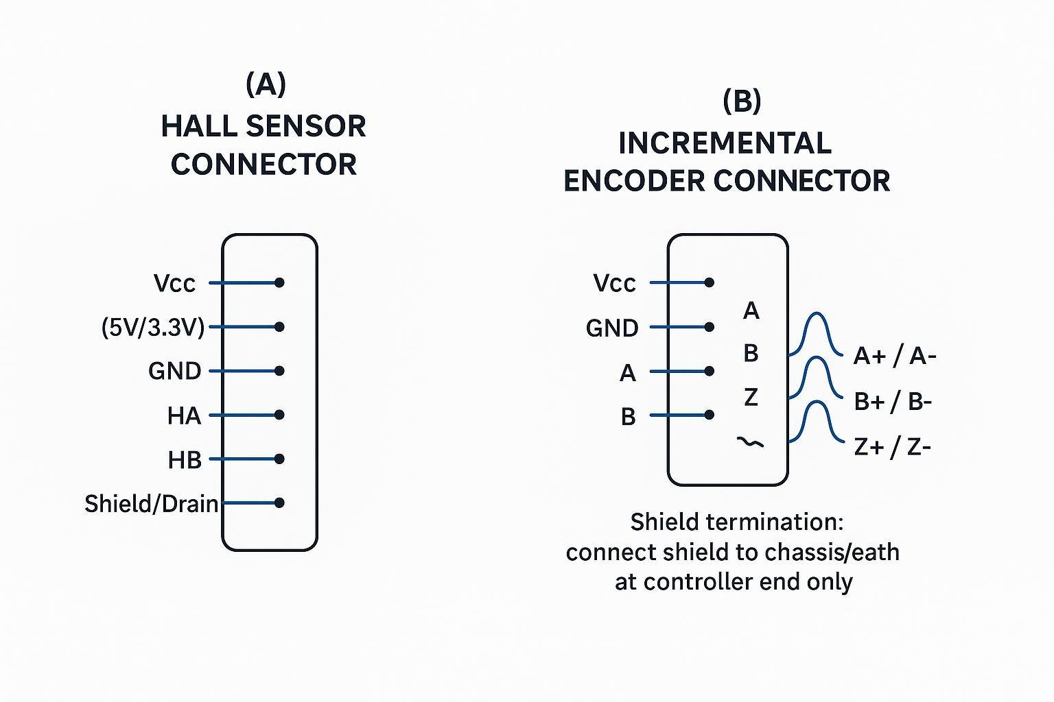
Hall sensors: power, outputs, and logic levels
Hall sensors typically use three digital outputs (often labeled HA/HB/HC) plus power and ground. Output types matter for Hall sensor wiring:
Open-drain/open-collector outputs need pull-up resistors.
Push-pull outputs typically do not.
Texas Instruments covers these output stages and how to interpret them in “Understanding and Applying Hall Effect Sensor Data Sheets” (SLIA086). For a practical starting point on pull-ups, SparkFun’s pull-up resistor guidelines reflect the common engineering rule of thumb (often ~10 kΩ as a starting value).
Wiring diagram checklist for Halls:
Label Hall supply voltage (5 V vs 3.3 V) and confirm logic-level compatibility at the controller input.
If open-drain: show pull-ups and where they live (on controller PCB vs in harness).
Show a clean reference ground for sensor returns (avoid sharing with high-current motor return in the harness where possible).
Incremental encoders: A/B/Z and differential options
Incremental encoders typically provide:
A and B quadrature channels (direction + counts)
Z index pulse (one per revolution)
This is the practical core of incremental encoder wiring: power/ground, A/B/Z (or A+/A-, etc.), and a shield strategy that keeps PWM noise out of the receiver.
In noisy environments or long cables, encoders often use differential line-driver outputs (A+/A-, B+/B-, Z+/Z-) aligned with RS-422-style receivers. That’s why the receiver side is typically designed around differential inputs (as described in the MAX14890E incremental encoder interface datasheet) and why many vendors recommend RS-422 differential links for robust signaling (see POSITAL’s incremental encoder interface overview).
Wiring diagram checklist for encoders:
Label whether outputs are single-ended (A/B/Z) or differential (A+/A-, etc.).
Specify the expected supply (5 V TTL vs 24 V HTL, if applicable).
Show twisted-pair assignments for each differential pair.
Shielding, pull-ups, and filtering practices
Sensor signals fail most often due to coupling from motor phase leads and PWM edges. Your diagram should make these practices explicit:
Use twisted pairs for differential signals (A+/A-, etc.).
Use shielded cable for feedback harnesses.
Terminate the shield deliberately—commonly to chassis/earth at the controller end—to avoid uncontrolled antenna behavior.
If you need a concise shield grounding explanation for mixed EMI environments, Celera Motion’s Grounding & Shielding Recommendations (TN-1202) is a practical reference.
3-wire and 4-wire brushless motor wiring and ESC hookups
Search results often mix three different things: (1) three-phase BLDC motors, (2) fan-style BLDC motors with an internal driver, and (3) ESCs used in drones/RC. A “complete” wiring checklist should separate them.
3-wire brushless motor wiring for fan-style BLDC
A typical 3-wire fan BLDC has an internal driver. The three leads are commonly:
V+ (supply)
GND
Control (often a PWM input, sometimes an analog voltage)
Key schematic notes:
Confirm the control pin’s electrical type: open-collector, push-pull, or pulled-up internally.
Don’t assume the PWM levels: some inputs want 5 V logic, others are 3.3 V tolerant.
Keep control return referenced to the same ground as the fan’s driver (avoid long ground offsets under load).
4 wire brushless motor diagram for fan-style BLDC
A 4-wire fan BLDC usually adds a tach/sense output:
V+
GND
PWM/Control
Tach (speed feedback, often open-collector)
Practical wiring implications:
If the tach is open-collector, you need a pull-up on the controller side.
Treat the tach lead like a low-level signal: route away from high di/dt motor power wiring.
3-phase ESC wiring for BLDC motors
An ESC wiring diagram normally contains:
Battery input to the ESC (V+ and GND)
Three phase outputs from ESC to motor (often not labeled U/V/W on hobby ESCs)
Control input (commonly RC-style PWM)
Direction is typically changed either in firmware/config or by swapping any two phase wires. If the ESC supports sensor inputs (not all do), document the Hall connector and mapping just like a BLDC controller harness.
Internal resources you may want alongside this section:
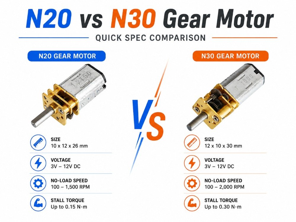
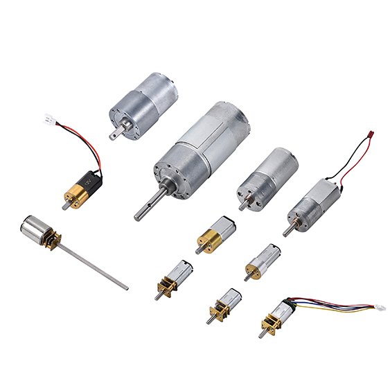
For selecting a compact gearmotor/BLDC assembly, see INEED’s small gear motor range.
For common application integration notes, start from INEED Motors’ product homepage and follow the relevant motor family pages.
Protection, power integrity, and EMC
This is the section that prevents “it worked on the bench” from becoming “it fails in the chamber” or “it fails in the harness.” Treat protection and EMC as part of the wiring diagram, not a separate document.
Reverse-polarity, fusing, and TVS selection
A wiring diagram for motor power should show protection devices in order, with reference designators and ratings guidance:
Fuse near the power entry to limit fault energy.
Reverse-polarity protection (often an ideal-diode MOSFET approach for lower loss than a series diode).
TVS diode close to the connector to clamp transients.
For EMC-oriented placement and low-inductance routing guidance (especially for TVS and return paths), ST’s AN4694 EMC design guide for motor control (2015) is a solid baseline.
Decoupling, snubbers, and cable filters
Motor drivers switch high currents quickly, so the wiring diagram should explicitly call out where the energy is buffered and where noise is suppressed:
Local ceramics at the motor driver supply pins (high-frequency decoupling).
Bulk capacitance sized for load steps and braking energy.
Snubbers (RC) or ferrites where your validation shows overshoot or ringing.
Cable ferrites/filters as a harness-level knob for conducted/radiated emissions.
Layout and decoupling details matter enough that they should be referenced even in a wiring guide; TI’s SLVA959 motor driver layout best practices provide concrete placement principles (minimize loops, place capacitors tight to pins, control high di/dt current paths).
Layout, grounding, and standards references
A “complete” wiring diagram includes grounding intent. At minimum:
Show the power return path separately from sensitive signal grounds.
Show where shields land (chassis/earth vs signal ground) and whether it’s single-point.
Keep motor phase leads physically separated from encoder/Hall harnesses.
For EU-oriented product teams, the motor-drive EMC product standard EN 61800-3 is commonly referenced during compliance planning (your compliance team will decide applicability based on the final product category).
Engineering support and RoHS/REACH documents are available (By INEED Motors).
Downloadable SVG wiring diagrams
We publish downloadable wiring assets on our Downloads page. Visit Downloads: DC motor diagram and wiring SVGs for the latest files.
What you’ll find there (updated as new diagrams are added):
Brushed DC two-wire polarity + H-bridge states
BLDC three-phase U/V/W with optional Hall connector
3 wire brushless motor wiring (fan-style) and 4 wire brushless motor diagram (fan-style)
3-phase ESC wiring overview
Conclusion
The wiring difference between “a diagram that looks right” and “a diagram that ships” is whether it communicates behavior, failure modes, and verification points.
For brushed DC, make polarity and braking states explicit, and ensure your H-bridge interface (IN1/IN2 vs PH/EN) matches the control behavior you actually need. For BLDC, document phase order assumptions and keep safe switching and ground separation in mind early.
Next steps:
Validate every connection against your motor and driver datasheets before applying power.
Instrument early EVT/DVT builds (scope the motor terminals, measure current, and confirm sensor logic levels under PWM).
Run pre-compliance thinking early—grounding, shielding, and decoupling are hard to “patch” after harnesses are frozen.
If you need a second set of eyes on a harness + pinout package, an application review from INEED Motors engineering support can help catch miswire risks before DVT build release.
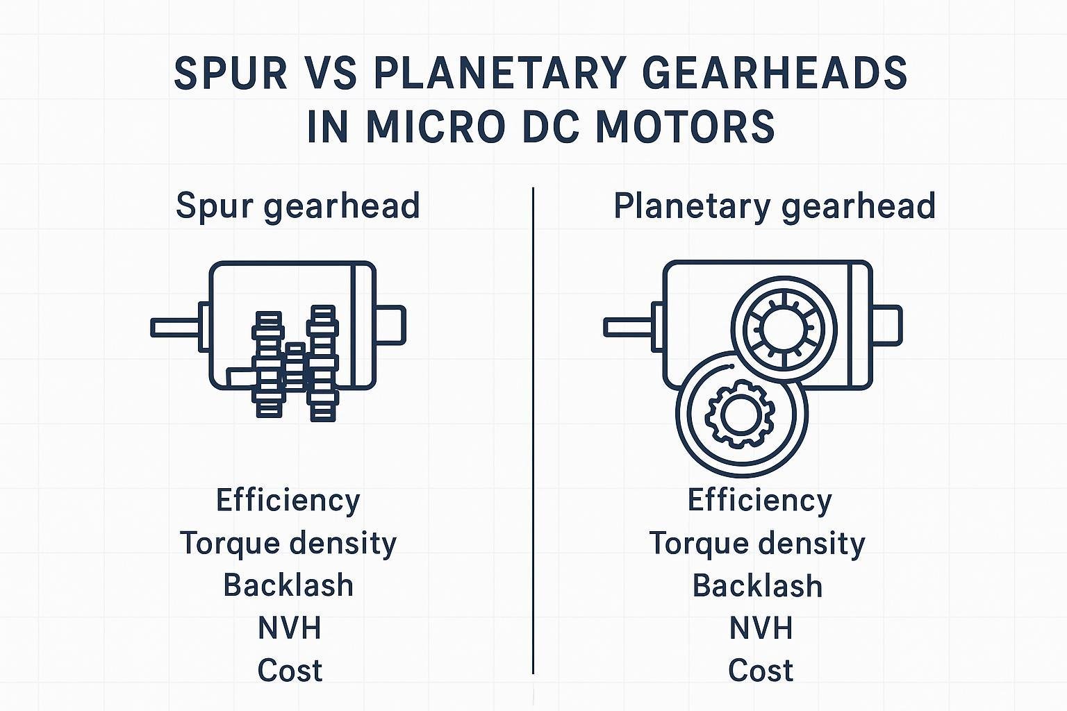
If you’re selecting a motor + feedback stack (BDC/BLDC, encoder options) and want the wiring and documentation to match your DVT plan, INEED’s spur geared motors integration notes, planetary gear motors options, and the broader small gear motor catalog are good starting points.
FAQ
What is a dc motor schematic vs a dc motor wiring diagram?
A dc motor schematic focuses on electrical function (symbols, switching devices, protection parts, and how current flows). A dc motor wiring diagram focuses on implementation (connector pin numbers, wire IDs, harness routing, and what you should measure at test points). In EVT/DVT, you typically need both: the schematic to validate behavior, and the wiring diagram to prevent miswires.
How do I read a brushless motor wiring diagram for a three-phase BLDC?
Look for three phase outputs (U/V/W) from the controller to the motor, then check whether feedback is separate (Hall/encoder connector). A practical brushless motor wiring diagram should also state how direction is defined and how reversal is achieved (swap any two phases or command reverse in firmware), plus where power ground and signal ground are tied.
Why does a 4 wire brushless motor diagram look different from a 3-phase BLDC diagram?
A “4 wire brushless motor diagram” often refers to a fan-style BLDC with an internal driver: V+, GND, PWM/Control, and Tach. A three-phase BLDC diagram uses three power phases and usually has a separate feedback harness. Mixing these categories is a common reason motors don’t start or tach signals look wrong.
What is 3 wire brushless motor wiring in practice?
Most 3-wire brushless motors in products are fan-style BLDC units with built-in electronics. The third lead is typically a speed control input (PWM or analog). The key is to confirm the input type and logic level in the motor datasheet before you connect it directly to an MCU pin.
What should an ESC wiring diagram always show before first power-on?
At minimum: battery polarity and protection on the input side, the three phase connections to the motor, the control input type and signal ground reference, and a clear direction-reversal method. If the system includes sensors (Hall/encoder), document that connector and mapping separately so feedback wiring can be verified before closed-loop runs.