Introduction
If you’re sourcing a high torque gear motor in 2026, the hardest part usually isn’t finding a part number—it’s proving (early) that a high torque low speed motor will survive your duty cycle, hit torque at temperature, and pass EMC + EU documentation without schedule slip.
This guide gives you a practical, engineering-first sizing workflow (including T_rms), how to pick a gearbox architecture, what drives life and reliability, what validation data to request, and how to control sourcing risk under tightening compliance expectations.
It’s written for OEM engineers and sourcing managers working under strict QA, traceability, and EU compliance constraints—especially teams comparing a low rpm high torque motor option for 12V and 24V systems (including searches like best 12v high torque dc motor and most powerful 12 volt dc motor).
Why this matters in 2026: supply chains are still sensitive to MOQ/lead-time swings, and compliance teams increasingly expect clean REACH/RoHS declarations plus realistic EMC evidence at the system level—not just a datasheet.
Define and size correctly
Quick parameter comparison (INEED models)
Below is a practical comparison table using sample rows published on each product page. Because torque/speed/current vary by gear ratio and test point, treat this as a shortlisting aid and confirm the exact ratio + duty cycle with your supplier.
Model (linked) | Sample voltage | Sample no-load speed | Sample stall torque | Sample input power |
|---|---|---|---|---|
12V (ratio 1000 sample) | 11 rpm | 9000 g·cm | 12V × 220 mA = 2.64 W (stall, sample) | |
12V (ratio 1000 sample) | 22 rpm | 17600 g·cm | 12V × 17600 mA = 211.2 W (stall, sample) | |
12V (ratio 500 sample) | 44 rpm | 7800 g·cm | 12V × 800 mA = 9.6 W (stall, sample) | |
12V (ratio 500 sample) | 44 rpm | 8000 g·cm | 12V × 8000 mA = 96 W (stall, sample) | |
12V (ratio 1026 sample) | 14 rpm | 20000g.cm | See page | |
12V (ratio 1168 sample) | 15 rpm | 11200 g·cm | 12V × 540 mA = 6.48 W (stall, sample) | |
24V (ratio 500 sample) | 20 rpm | 10000 g·cm | 24V × 4000 mA = 96 W (stall, sample) |
Notes: “Sample input power” is calculated as V × I at the stall-current sample row shown on the product page. For buyer-side comparisons, also request rated/continuous current at your target torque and a thermal-rise test under your T_rms duty cycle.
Translate application to specs
Start by translating the application into a spec stack that purchasing and engineering can both defend:
Mechanical output needs: required torque at the load, required output speed (RPM), and motion profile (constant, intermittent, accel/decel, reversals).
Load type: continuous friction load vs gravity load (lift/hold) vs inertia-dominant load (indexing).
Environment and integration: ambient temperature, available airflow, allowable surface temperature, space envelope, mounting stiffness, and expected shock/vibration.
Electrical constraints: supply voltage window, current limits, and whether speed control is open-loop PWM or closed-loop.
Be explicit about what “high torque, low speed” means in your context. For one design it’s 3 N·m at 30 RPM in short bursts; for another it’s 0.6 N·m continuously at 60 RPM with low audible noise. Different definitions drive different motor constants, gearbox types, and validation tests.
Compute torque–speed and T_rms
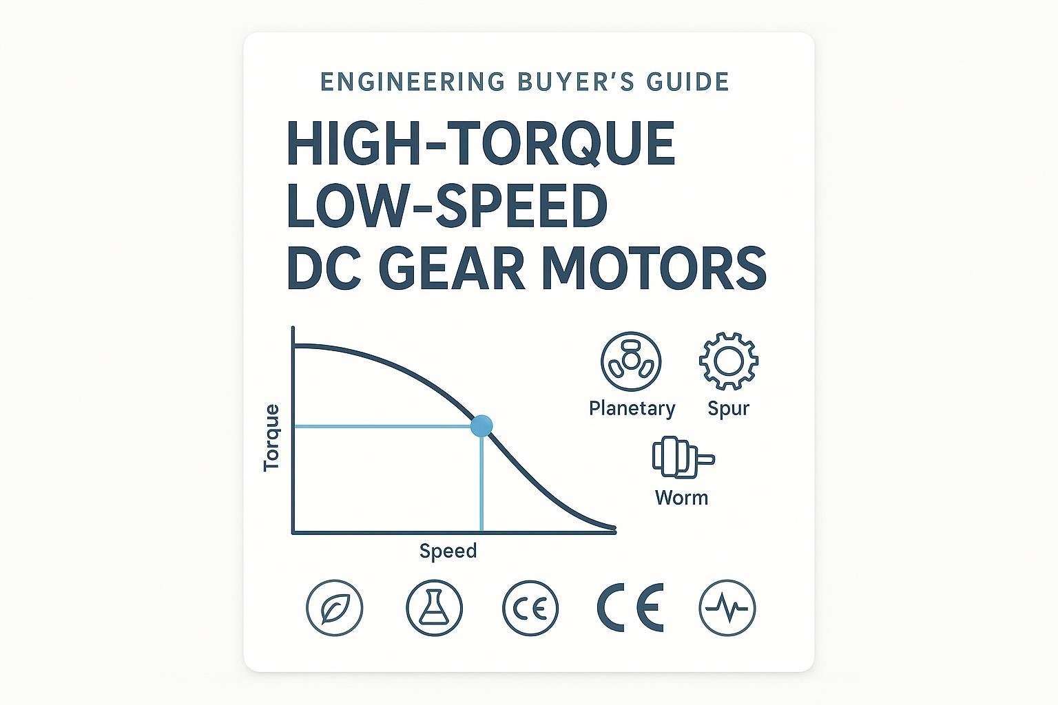
A DC motor’s torque–speed curve is approximately linear: torque drops as speed rises. Your gearbox shifts that curve by trading speed for torque (and adding losses).
The selection mistake to avoid is sizing only to peak torque. If your load is cyclic, thermal limits are dominated by RMS torque over the duty cycle.
Use the standard RMS approach described by Oriental Motor in their note on RMS torque calculation for duty cycles:
[ T_{rms} = sqrt{frac{sum (T_i^2 cdot t_i)}{T_{cycle}}} ]
Where each interval i has torque T_i applied for time t_i.
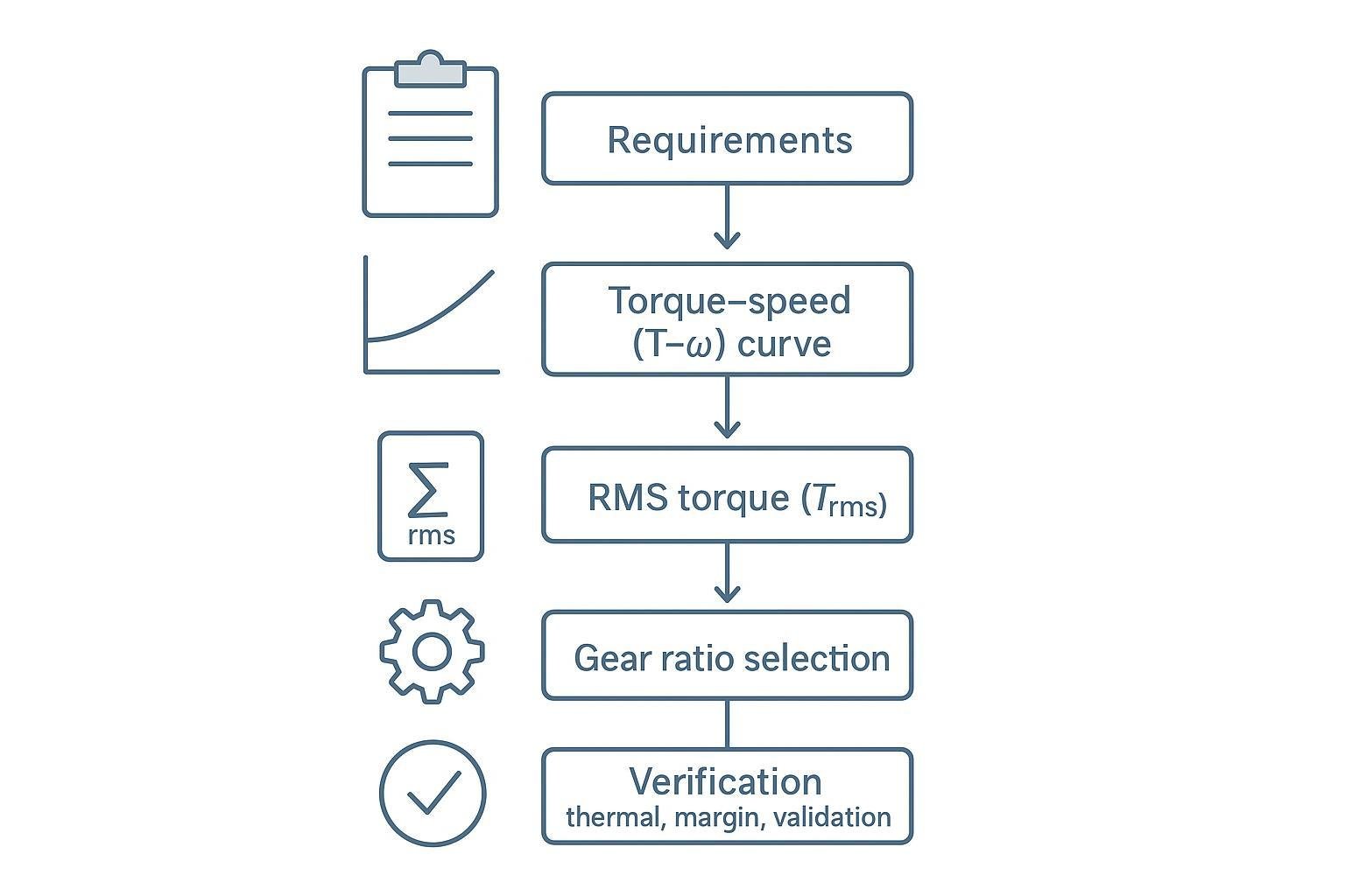
Practical workflow:
Build a simple duty-cycle table (accel, run, dwell, decel, hold) with torque and time.
Compute
T_rmsand compare it to the continuous torque capability of the geared motor at your worst-case ambient.Verify your operating point sits in a continuous region of the curve with margin (don’t live near stall unless the duty cycle is truly brief).
For load-torque calculation, Precision Microdrives provides a clear set of examples in torque calculations for gearmotor applications. The key is to separate:
load torque (gravity/friction)
acceleration torque (inertia × angular acceleration)
additional losses (seals, misalignment, gear efficiency)
Set safety, thermal, and voltage margins
Margins should be intentional, not a panic factor added at the end.
Safety factor on torque: apply a factor for friction uncertainty, wear, and worst-case loading (often 1.5–2.0× for industrial OEM use; higher for shock loads).
Thermal margin: use
T_rmsfor heating and reserve temperature headroom (motors that “meet torque” at 25°C can derate quickly at elevated ambient).Voltage margin: define the real supply window (brownout, battery sag, harness drop). A motor that only meets speed at nominal voltage will fail quietly in the field.
⚠️ Warning: If you can’t state the duty cycle in numbers, you don’t have a continuous torque requirement—only a guess. That’s the fastest path to overheated windings or premature brush/bearing wear.
Choose the right gearbox for a high torque low speed DC gear motor
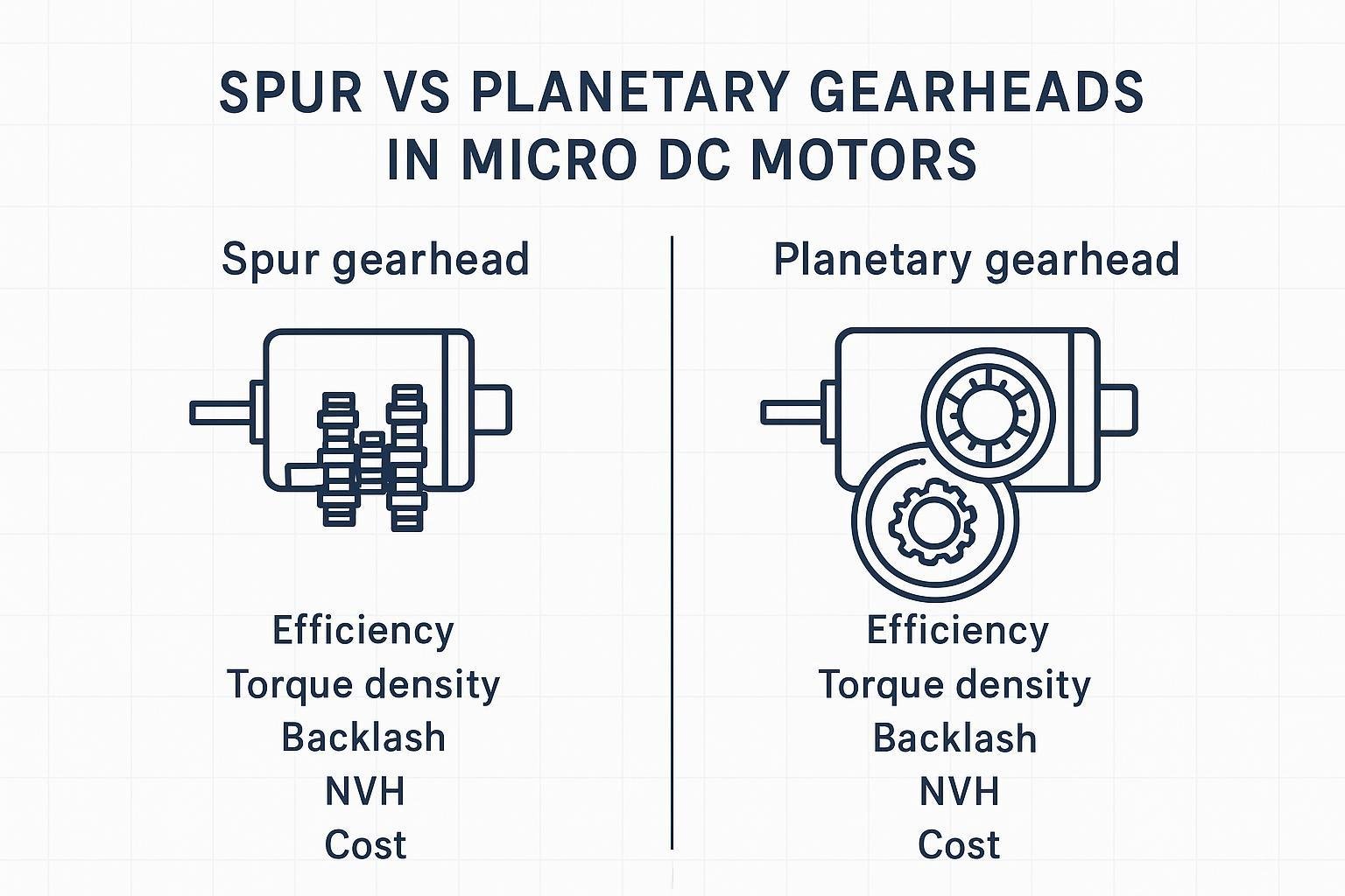
Planetary vs spur vs worm
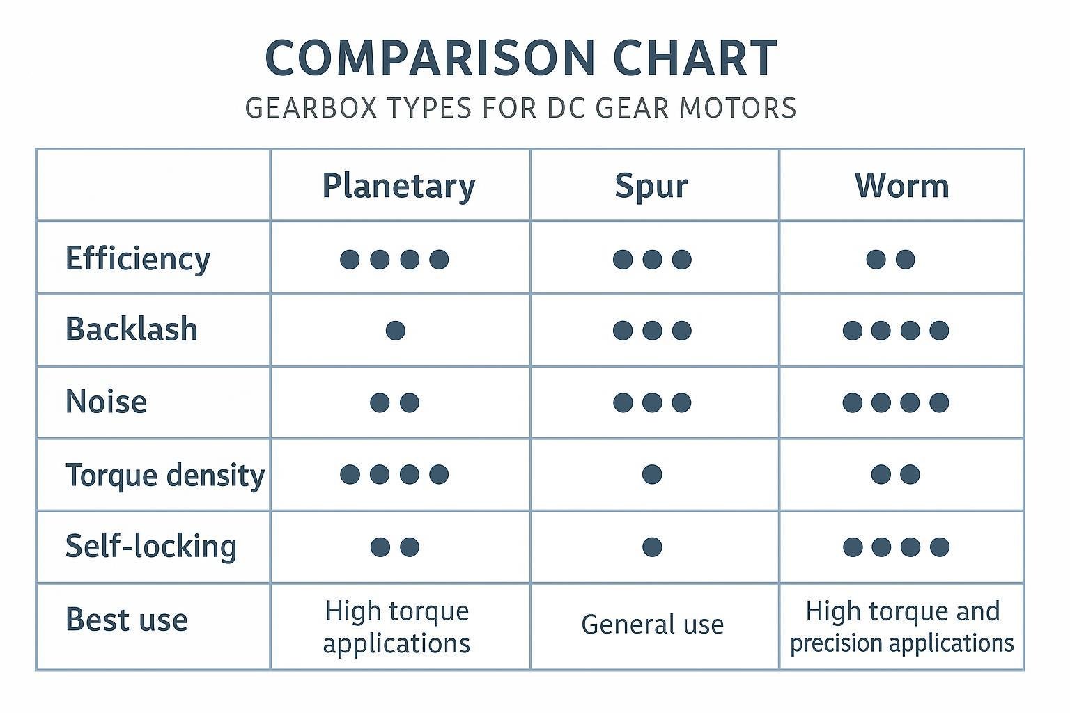
Gearbox selection is where “best motor” becomes “best system.” For high torque at low speed, your trade space is usually stiffness, efficiency, backlash, and packaging.
A useful starting point is understanding typical behavior by architecture. Technische Antriebselemente summarizes typical gearbox efficiencies by architecture (planetary and spur generally high per stage; worm often lower because it relies on sliding contact).
Planetary: high torque density in a coaxial package; good for compact, high-load applications where efficiency and stiffness matter.
Spur: simpler and often cost-effective; can be fine for lower loads or lighter duty cycles, but may be noisier and less torque-dense.
Worm: good for 90° layouts and can provide self-locking behavior in some configurations; typically lower efficiency and higher heat under continuous load.
For a practical qualitative view of backlash/noise/self-locking trade-offs, see SG Gearbox’s planetary vs spur vs worm gearbox trade-offs.
Gear ratio effects on RPM and efficiency
Gear ratio does three things at once:
Reduces output speed:
RPM_out ≈ RPM_motor / ratioIncreases output torque (minus losses):
T_out ≈ T_motor × ratio × η_totalChanges what the motor “sees”: reflected inertia scales with the square of the ratio.
Two practical implications for buyers:
Efficiency compounds by stage. Even if each stage is efficient, multi-stage reductions multiply losses.
High ratios increase thermal risk when the motor runs near stall or in high-current regions for long periods.
Backlash, noise, and self-locking
These are the “quiet” requirements that create late redesigns.
Backlash matters for bidirectional positioning, camera gimbals, latches, and any control loop trying to hold a target. Specify a backlash target (or a maximum) and ask how it’s measured.
Noise is not just a comfort metric. Gear noise can signal poor mesh, lubrication issues, or housing resonance. If noise is critical, request dBA data with distance, load, and speed defined.
Self-locking (often associated with worm gear sets) can reduce the need for brakes, but don’t assume it is guaranteed: geometry, lubrication, and wear can change back-driving behavior.
Application scenarios: what “high torque, low speed” means in the real world
A spec-only comparison is rarely enough. The same “high torque low speed motor” requirement can mean very different gearbox choices once you factor in backlash, duty cycle, and safety expectations.
Robot arms and grippers
Robot joints and end-effectors typically care about repeatability, low backlash, and predictable thermal behavior during repeated cycles.
Planetary gearboxes are often a good starting point when you need compact torque density and stiffness. For compact joints, shortlist families like the 16mm planetary gear motor or a 16mm planetary gear brushless motor when lifetime and closed-loop control requirements push you toward BLDC.
Medical devices
Medical equipment often has a different “triangle”: low noise, reliability, and documentation readiness (materials, traceability, change control). Low vibration and smooth startup matter as much as peak torque.
For compact, low-noise mechanisms, a coreless motor + gearbox can be attractive, depending on your load and duty cycle. Use options like the 12mm coreless gear motor as a shortlist candidate when acoustic/feel and smoothness are top priorities.
Industrial automation
Industrial fixtures and actuators often need robust margins for continuous T_rms, shock loads, and environmental stress. Here, the buying risk is usually thermal and QA consistency.
If you need a compact coaxial drive with good efficiency, planetary remains a common default (for example, the 24V DC planetary gear motor for 24V systems). If the mechanics require a right-angle drive or you benefit from resistance to back-driving, worm gear options like the 370 worm drive motor can be relevant—just treat efficiency/heat as first-class constraints.
Electric wheelchairs and mobility aids
Mobility platforms are dominated by safety, sustained load, and real-world supply variation (battery sag, hills, starts/stops). Teams often search for the “best 12v high torque dc motor” or “most powerful 12 volt dc motor,” but the engineering reality is that continuous torque at temperature and system efficiency determine range and reliability.
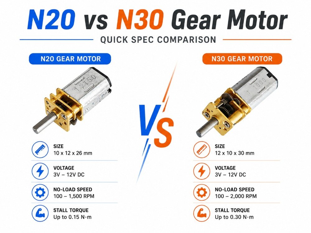
Where packaging permits, higher power platforms may shortlist larger gearmotor families such as the 775 planetary gear motor. For compact auxiliary functions (latches, recline mechanisms, small pumps), an N20-size family such as the 12mm N20 micro gear motor may be a better fit.
Ensure reliability and life
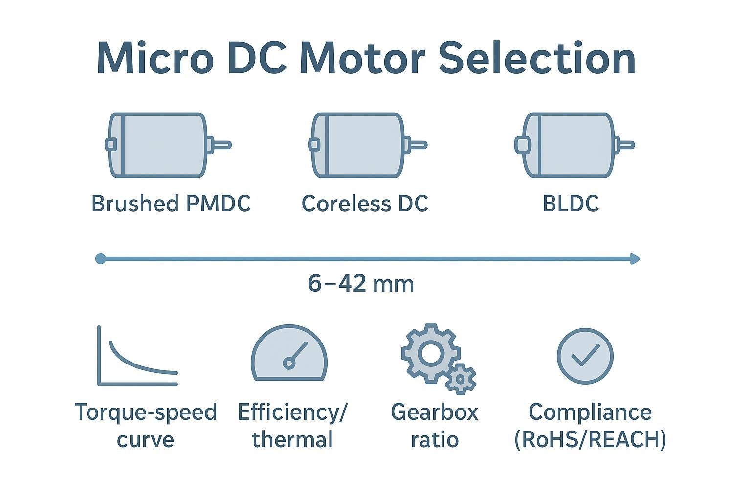
Brushed vs BLDC and MTBF
The brushed vs BLDC decision is a reliability and control decision as much as a performance decision.
Brushed DC: simpler drive electronics and often lower system cost; life can be limited by brush/commutator wear, especially at high current, high temperature, or frequent start/stop cycles.
BLDC: removes brush wear from the equation, but shifts risk into electronics (driver quality, hall/encoder reliability, tuning, and EMC integration). It’s often the better fit when your duty cycle is heavy and lifetime expectations are high.
MTBF only helps when it’s tied to conditions: load, speed, ambient, duty cycle, and what “failure” means. Ask for life-test conditions and failure criteria, not a single MTBF number.
Bearings, lubrication, and heat
In high-torque low-speed operation, heat is often generated by current (copper losses) and gearbox losses. That heat then accelerates wear.
Buyer checks that prevent surprises:
Bearing type and load ratings (including overhung and axial loads if your output has belts/gears).
Gearbox lubrication type and temperature range; whether re-lube is possible or sealed-for-life.
Thermal path: motor housing contact to your chassis, airflow assumptions, and allowable winding temperature rise.
IP rating, shock, and duty cycle
IP rating is only meaningful with test conditions. If the motor is exposed to washdown, dust, or intermittent immersion, confirm the exact IP level needed and any connector/cable entry requirements.
For shock and vibration, ensure the supplier can provide results from realistic profiles (not a generic “passed vibration test”). Match the test to your use case: handheld devices, mobile robotics, industrial machinery, or medical equipment all differ.
Engineering selection formulas (copy/paste-ready)
Use these formulas to translate your mechanism into a defensible motor/gearbox requirement. Symbols are defined inline; keep units consistent.
1) Total load torque at the output shaft
Break output torque into components:
[ T_{out}(t)=T_{load}(t)+T_{acc}(t)+T_{loss}(t) ]
Common terms:
Friction + constant load: (T_{load}=Fcdot r) (force at radius) or (T_{load}=m g r) (gravity load)
Acceleration torque: (T_{acc}=J_{out},alpha) where (alpha) is angular acceleration
2) RMS torque over a duty cycle (thermal sizing)
[ T_{rms}=sqrt{frac{sumleft(T_i^2,t_iright)}{T_{cycle}}} ]
Use T_rms to size heating; use peak torque for structural checks.
3) Gear ratio and efficiency chain
Approximate relations:
Output speed: (omega_{out}approx omega_{m}/G)
Output torque: (T_{out}approx T_{m},G,eta_{gb})
Reflected inertia to the motor: (J_{ref}approx J_{out}/G^2)
Where (G) is gear ratio and (eta_{gb}) is gearbox efficiency (treat as a product of stages).
4) Output power and efficiency
Mechanical output power:
[ P_{out}=T_{out},omega_{out} ]
Electrical input power:
[ P_{in}=V,I ]
System efficiency estimate:
[ eta_{system}approx frac{P_{out}}{P_{in}}=eta_{motor},eta_{gb},eta_{drive} ]
5) A compact worked example (structure, not numbers)
Compute (T_{load}) from your force + radius.
Compute (T_{acc}) from inertia and desired accel time.
Add a loss term (or margin) and get a time-profile (T_{out}(t)).
Calculate (T_{rms}).
Choose a ratio (G) that puts the motor in a continuous region at your worst-case voltage/temperature.
Verify current at (T_{rms}) stays within drive limits, then request dyno + thermal-rise tests under a matching duty cycle.
Validate performance and EMC
Dyno maps and thermal rise tests
For a buyer’s guide mindset, the question is: what evidence should you ask for before you lock the design?
Minimum useful data for a high-torque low-speed DC gear motor:
Torque–speed map (or at least key points) at defined voltage and temperature
Current vs torque curve (to estimate drive sizing and heating)
Thermal rise test at your representative duty cycle (or a conservative surrogate)
When you review dyno data, check that test conditions match reality: mounting, airflow, and whether the gearbox was at steady-state temperature.
Life, vibration, and environmental tests
If the application is critical, push validation earlier than you think you need:
Life test plan: cycles, loads, speed, reversals, and pass/fail criteria
Vibration/shock: profiles and fixtures that resemble your mechanical integration
Environmental: temperature cycling, humidity, corrosion exposure if relevant
A supplier who can describe test fixtures, sample sizes, and failure modes is usually more reliable than one who only shares a marketing slide.
Emissions/immunity basics for drives
In most real systems, the motor alone isn’t the EMC problem—the drive and wiring are.
Basics that reduce risk:
Treat PWM edges as RF events: minimize loop area, use proper grounding, and keep motor leads short where possible.
Plan for filtering and shielding early (ferrites, common-mode chokes, cable shields) rather than “adding it later.”
Validate with the full harness and enclosure, because cable routing can dominate radiated emissions.
Compliance and documentation
RoHS/REACH and material declarations
For EU shipments, compliance is not a statement—it’s a set of documents that must survive an audit.
RoHS: ensure restricted substances and exemptions are handled correctly. The European Commission’s overview of the EU RoHS directive requirements is a good baseline reference for what the directive covers.
REACH: if substances of very high concern (SVHC) are present above thresholds, you need supply-chain communication and updates over time.
Practical sourcing tip: ask for a material declaration format your compliance team can ingest (IPC-1752A or an equivalent structured declaration), plus change-control expectations when sub-suppliers change.
CE, DoC, and technical files scope
A common confusion: components don’t always carry CE marking in the way finished equipment does.
As the integrator, you typically own:
system-level EMC evidence
the final Declaration of Conformity (DoC)
the Technical File that explains design choices, risk assessment, and test reports
As a component supplier, a motor vendor should be able to provide supporting evidence (test reports, materials declarations, and specifications) that you can place into your Technical File.
Machinery Regulation and LVD notes
Two notes to keep your 2026 programs out of trouble:
LVD scope: electrical safety requirements apply based on voltage ranges; define whether your end product falls under LVD and which harmonized standards you’ll use.
Machinery Regulation transition: if your product is “machinery” or part of machinery, you should plan for the transition from the Machinery Directive to the new regulation. Intertek’s overview of the EU Machinery Regulation transition timeline highlights why teams should update risk assessments and documentation practices before 2027.
Sourcing and risk control
Lead times and MOQs by phase
Treat lead time and MOQ as phase-dependent constraints:
Prototype/EVT: you need responsiveness and small-batch flexibility.
DVT/PVT: you need stable process windows and repeatable testing.
MP: you need capacity planning, controlled change management, and predictable logistics.
Don’t let procurement lock an MOQ that forces you into early inventory risk before the design is validated.
QA systems, PPAP, and traceability
Even when you don’t run formal automotive PPAP, you can borrow the mindset:
define critical-to-quality (CTQ) dimensions (shaft concentricity, backlash, no-load current, noise)
request process controls and inspection records
require lot traceability (materials, winding batches, gear sets)
If a supplier can’t explain their end-of-line testing, you’re buying uncertainty.
Total cost levers and buffers
A “cheap” geared motor can be expensive when you add:
engineering rework (EMC fixes, thermal redesign)
scrap and RMA handling
line downtime from inconsistent fit or noise failures
Buffers that often pay for themselves:
dual-source critical variants (even if only at the drawing level)
pre-booked capacity for ramp periods
incoming QA sampling plans aligned to risk (not blanket 100% re-test)
Conclusion
You’ll make better high torque low speed DC gear motor choices when you size using T_rms and explicit margins, match the gearbox architecture to your precision/efficiency needs, and validate early with dyno/thermal, life, and EMC evidence—then document it cleanly for EU compliance and internal QA.
Next steps: align compliance expectations early (REACH/RoHS declarations, system-level EMC plan), lock QA evidence and traceability requirements before you commit to MOQs, and plan supplier capacity for your ramp.
If you’re already shortlisting candidates, jump straight to a relevant family page and confirm ratio options + validation data:
Compact planetary options: the 16mm planetary gear motor series and the 16mm 12V planetary gear motor option
Right-angle / back-driving-sensitive mechanisms: the N20 micro worm gear motor or 370 worm drive motor family
FAQ
1) What’s the difference between “stall torque” and “continuous torque” for a low RPM high torque motor?
Stall torque is the peak torque at zero speed, and it usually comes with the highest current draw and fastest heating. Continuous torque is what the motor + gearbox can deliver without overheating under your real ambient and mounting conditions. For selection, treat stall torque as a short-duration structural check, and use T_rms (and thermal-rise data) to validate continuous operation.
2) How do I compare candidates when each model has many gear ratios?
Pick one or two target operating points (output RPM and required output torque at temperature), then map each candidate’s gear ratio to that point. Ask for the supplier’s dyno curve or key datapoints at the same voltage and test method. If you only compare “best-case” ratios across vendors, you’ll end up with an apples-to-oranges shortlist.
3) For a 12V design, what matters more: “most powerful 12 volt DC motor” or system efficiency?
In battery-powered products, sustained torque at temperature and system efficiency usually matter more than a single “most powerful” claim. A higher-efficiency motor/gearbox running in a continuous region can outperform a higher-stall-torque option once you include battery sag, driver limits, and heat.
4) When should I consider worm gearing for high torque low speed motor applications?
Consider worm gearing when you need a right-angle layout, compact packaging, or resistance to back-driving. The trade-off is typically lower efficiency and higher heat under continuous load, so validate with thermal-rise and duty-cycle testing and don’t assume self-locking is guaranteed in every condition.
5) What validation data should I request before locking the gearmotor?
At minimum, request torque–speed/current data at defined voltage and temperature, plus a thermal-rise test matched to your T_rms duty cycle. For regulated markets, also request materials declarations (RoHS/REACH) and clear change-control/traceability documentation so compliance doesn’t become a late surprise.
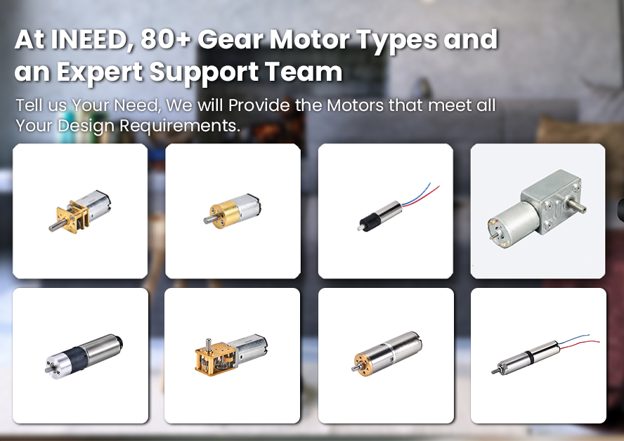
Customization and integration support
INEED Motors can support rapid engineering review and practical customization—shaft geometries, connectorization, and encoder options—so your integration and verification plan matches real duty cycles and EMC constraints.