Introduction
DC motor lifespan numbers vary because they often hide the two things that matter most: operating conditions and your definition of failure. A motor that runs at light load in a stable, clean environment can meet its functional requirements for a long time. The same motor, run near stall, hot, dusty, or with repeated shock loads, can “die early” even if the datasheet looks fine.
In practice, end of life is rarely a single dramatic event. It’s usually the point where the motor can’t meet your limits anymore—torque, speed, efficiency/current draw, temperature rise, or even noise and backlash.
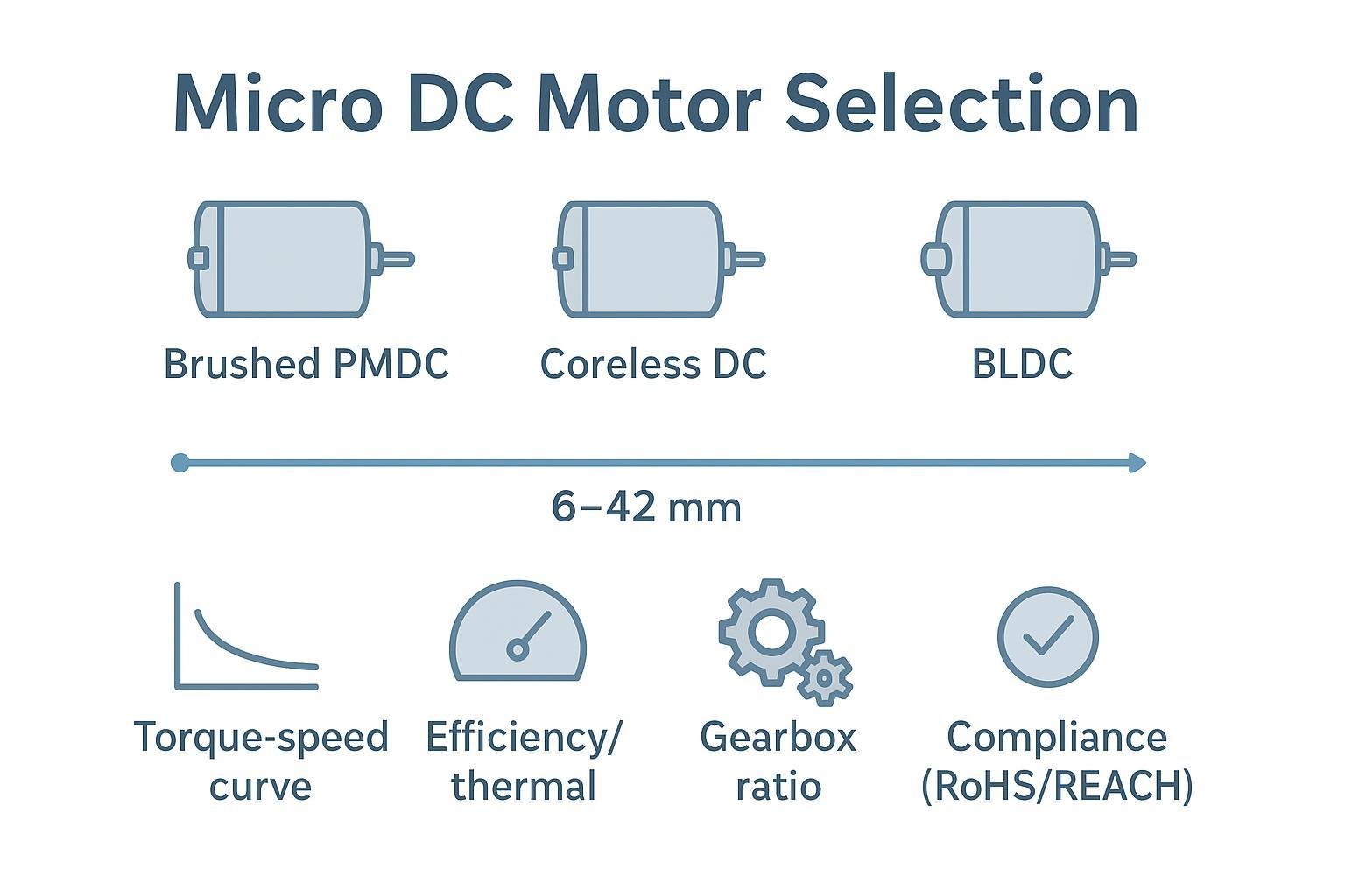
What counts as failure depends on the architecture and your product requirements:
Brushed motors: brush wear, commutator wear/contamination, or arcing that drives unstable current and heating.
Brushless motors (BLDC): bearing wear, insulation stress from heat, or system-level issues like grounding and drive setup that accelerate bearing or winding damage.
Small gearmotors: gearbox wear, lubrication breakdown, tooth damage from shock/stall, and backlash growth that eventually exceeds your positional or noise budget.
This guide gives you (1) realistic lifetime ranges by motor type, (2) the life drivers that usually dominate in the field, and (3) a validation approach you can use in sizing, procurement, and verification.
If you’re sizing a motor, use this as a sanity check against optimistic “hours” claims. If you’re sourcing, use it to request the right test conditions and acceptance criteria. If you’re validating, use it to design tests that actually resemble your duty cycle.
Lifespan by motor type
Brushed DC: ranges and limiting factors
For brushed DC motors, the wear mechanism is built into the design: brushes ride on a commutator. That friction (and the electrical contact) makes brushed lifespan more sensitive to speed, load, and contamination than many teams expect.
A commonly cited “typical” life range for small brushed DC motors is on the order of 1,000–3,000 operating hours, but that number only means something if the test conditions (load, speed, duty cycle, temperature) are similar to your application. In practice, brushed DC motor life is dominated by how cleanly the motor commutates at your load and how much thermal margin you have.
The main limiters are:
Brush and commutator wear/contamination. Monolithic Power notes the fundamental point: brushes and commutators experience mechanical wear, and even with replaceable brushes the commutator eventually wears as well (see Monolithic Power’s brushed vs. brushless DC motor explainer).
Thermal overload margin. A brushed motor run hot tends to wear faster (brush material behavior, commutation quality, and insulation aging all degrade with heat).
Bearing and lubrication quality. In many real systems, bearings still end up as a dominant failure contributor. HECO’s failure-mode summary for motors (broadly) highlights bearings as involved in a large fraction of issues (see HECO’s breakdown of common motor failure modes (bearings involved in 51%+ of issues)).
⚠️ Warning: “It ran in the lab for 1,000 hours” is not a lifespan claim unless the lab test captured your real duty cycle, mounting, temperature rise, and shock/load events.
BLDC: bearing-limited life at proper loads
BLDC motors remove the brush/commutator wear path, which often shifts the dominant limiter to bearings, lubrication, and heat management.
If your mechanical loads are within spec and your thermal margin is healthy, BLDC lifetime can be significantly longer than brushed architectures. But “no brushes” doesn’t mean “no failure.” In small BLDC designs, the common ways BLDC motor lifetime is shortened are:
Bearing fatigue or lubricant degradation (especially at higher speeds or elevated temperatures).
Thermal stress on insulation systems (hot windings age faster; magnets can also be affected at high temperatures in some designs).
Electrical stress and grounding issues that create circulating currents or other conditions that can damage bearings or windings.
The practical takeaway: BLDC life is usually less about a single wear item and more about keeping the whole system inside safe operating limits—load, alignment, temperature rise, and electrical stress.
Small gearmotors: gearbox wear, backlash growth, shock
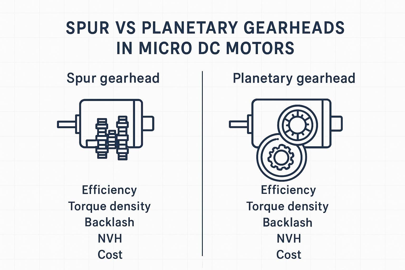
Small gearmotors add a gearbox, so you now have two coupled life systems: the motor and the gear train. Even if the motor itself could run longer, the gearbox can define end of life when backlash, noise, or efficiency drift beyond your limits.
Common gearbox-driven limiters include:
Tooth surface wear and pitting over time under load.
Backlash growth (especially relevant for positioning, latching, and quiet consumer devices). In other words, gearbox backlash that is acceptable when new may become a functional or noise limit later.
Shock loading and stall events that break teeth or overload shafts.
External radial/axial loads introduced by assembly or the mechanism—many small gearboxes are not designed to carry significant side loads.
Precision Microdrives’ application note on lifetime failures emphasizes practical failure causes like overload/stall, shock, contamination, and unintended axial/radial loading (see Precision Microdrives’ overview of DC motor and gearmotor lifetime failure modes).
Extend life with engineering levers
Thermal and load management for DC motor lifespan
If you want a longer DC motor lifespan, start with thermal and load margin. Most “mystery early failures” trace back to a motor spending more time near high torque (and therefore high current) than the design assumed.
Practical levers:
Derate torque and speed for continuous duty. If your load profile includes frequent peaks, evaluate RMS torque/current—not just peak.
Design the heat path. Small motors rely heavily on conduction into the housing/bracket. If the motor is isolated by plastic, foam tape, or poor contact, temperature rise can jump.
Set a thermal acceptance limit tied to insulation class. As an engineering reference point, IEC-style insulation class and temperature rise limits are often used to frame allowable operating temperatures. An accessible overview of IEC 60034-1 temperature-rise limits by insulation class is summarized in this IEC 60034-1 temperature-rise table overview.
A good habit is to treat thermal margin as a first-class spec: your measured operating temperature (ambient + rise) should sit meaningfully below the insulation class limit, not “just under it.”
Electrical stress control and shock mitigation
Electrical stress and mechanical shock are the two accelerants that quietly erase lifetime.
Electrical levers:
Current limiting to prevent prolonged stall/near-stall conditions.
Soft-start / controlled acceleration ramps to reduce peak torque shocks into the gearbox.
Commutation quality (brushed) or drive tuning (BLDC) to reduce arcing, ripple torque, and unnecessary heating.
Grounding/EMI practices (BLDC systems) to avoid conditions that can contribute to bearing damage.
Mechanical levers:
Limit hard stops. If your mechanism repeatedly slams into an end stop, the gearbox is doing impact work.
Add compliance (couplers, elastomer elements, controlled decel) so shock energy doesn’t go straight into teeth and bearings.
Avoid unintended side loads by using proper bearing support in the mechanism rather than forcing the gearbox output shaft to carry radial loads.
Environment, sealing, lubrication, and monitoring
Environment is where lab-life estimates go to die.
Dust and particles can contaminate commutators (brushed) and accelerate bearing and gear wear.
Moisture can reduce insulation resistance and promote corrosion.
Lubrication is a design variable, not a footnote: grease type, fill amount, and temperature range affect both noise and wear.
Monitoring doesn’t have to be complex. Even simple checks during validation—temperature rise at worst-case duty, current signature changes, audible noise growth, and backlash measurement—can provide early warning before field failures.
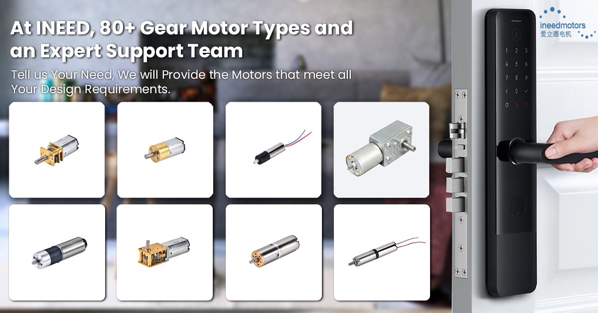
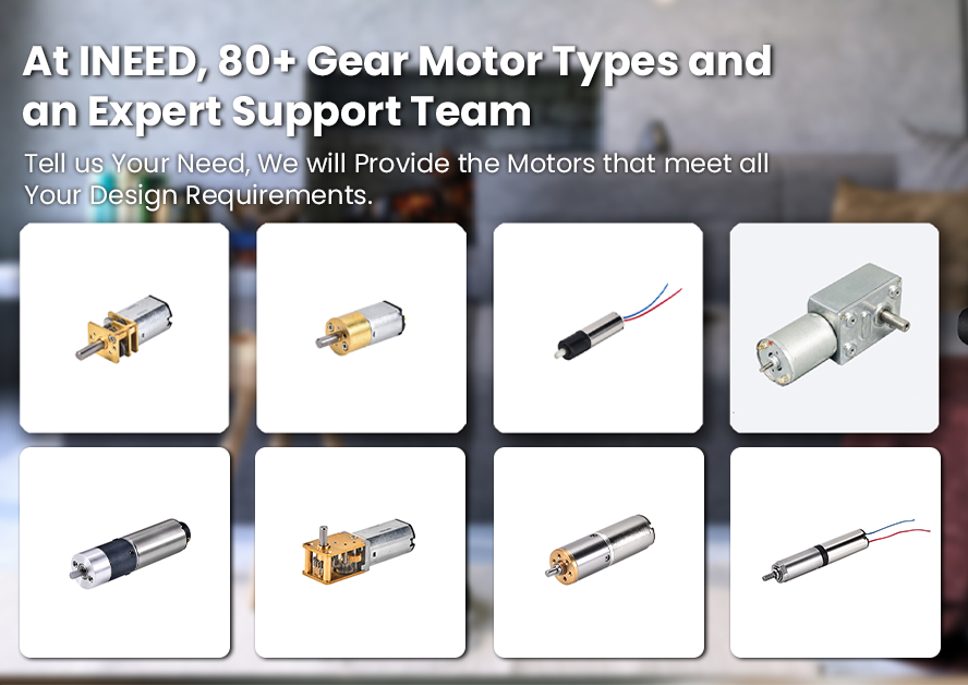
In support-heavy projects, it can also help to involve a supplier early to review duty cycle, mounting, and environment assumptions. For example, INEED Motors typically supports application-level checks such as recommending appropriate gear ratios, shaft/interface options, and (when needed) integrating add-ons like encoders—useful when your lifetime target is sensitive to alignment, shock, or thermal margin.
Validation, standards, and supplier data
Map the standards: IEC/UL/ISO and medical context
There isn’t one single “motor lifespan standard” that guarantees a life number, but there are standards that help you define and communicate test conditions and calculation methods.
A practical map:
IEC 60034-1 is commonly referenced for rotating machine rating concepts and temperature-rise framing.
IEC 60085 is widely referenced for insulation thermal classes and thermal aging framing.
ISO 281 is the standard basis for rolling bearing life calculations (L10/L10h), which can be useful when bearings are expected to be the life limiter.
UL 1004 is a safety standard family for motors (important for compliance, but not a service-life calculator).
If you’re in a medical or other compliance-heavy program, the key isn’t to “claim compliance” inside a blog post. It’s to ensure your qualification plan can produce the evidence your quality system needs: test conditions, traceability, acceptance criteria, and change control.
Plan life tests and define acceptance criteria
A lifespan test that doesn’t represent your duty cycle is usually just an expensive warm-up.
Plan your life test around:
Representative duty cycle (including starts/stops, peaks, dwell times).
Representative mounting and heat sinking (the thermal path is part of the system).
Representative load and shock events (if the mechanism has impacts, the test should too).
Representative environment (dust, humidity, temperature range).
Define acceptance criteria that match end-of-life in your product. Typical examples:
Torque/speed at a defined load remains within tolerance.
No sustained overcurrent beyond a defined limit.
Temperature rise stays within your thermal margin.
Noise does not exceed a specified threshold.
Backlash remains within an allowable band (critical for gearmotors).
Where bearing life is part of your reliability argument, you can document how you calculated life using ISO 281 definitions and formulas; a clear, practitioner-friendly explanation of L10/L10h is available in this ISO 281 L10/L10h bearing life formula overview. When you see “bearing L10 life” in a bearing datasheet, treat it as a statistical fatigue-life reference under defined loads and speed—not a promise for your full motor-gearbox assembly.
Supplier data you should request
If you only ask for “lifetime,” you’ll usually get a number with missing context. Instead, request the data that makes the number meaningful:
Life test conditions: load, speed, duty cycle, ambient temperature, mounting method, run/stop profile.
End-of-life definition used: brush wear limit, bearing noise limit, backlash limit, torque retention, current increase threshold.
Gearbox details (gearmotors): gear material, lubrication type, backlash spec (new) and any wear allowance.
Bearing details: bearing type, lubrication, and any calculated life basis.
Quality controls: incoming inspection, end-of-line tests, and traceability approach.
Change control: how design/material/lubrication changes are communicated across production.
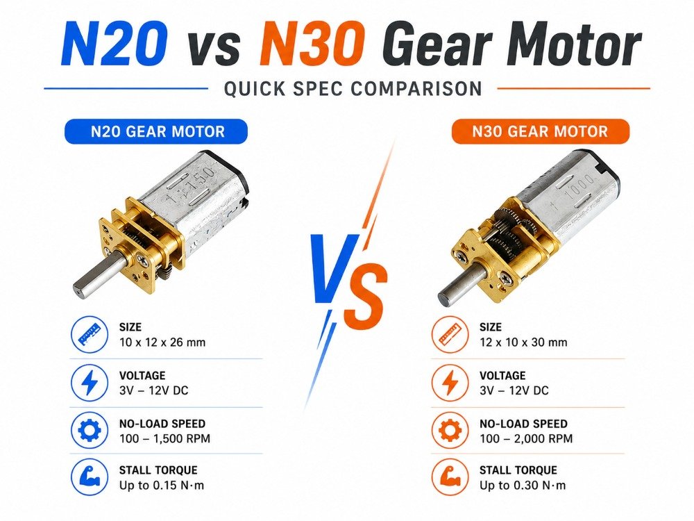
If you need a practical starting point for a gearmotor family, you can also reference a supplier’s product-page spec envelope to align terminology. For instance, INEED Motors planetary gear motors is a relevant internal reference point for gearbox form factor context and selection discussions.
Conclusion
Setting realistic life expectations starts with two decisions you control: what counts as failure, and what conditions your life estimate actually represents. Once those are explicit, the rest becomes engineering:
Brushed DC life is often limited by brush/commutator wear and heat.
BLDC life shifts the spotlight to bearings, lubrication, and system-level electrical/thermal stress control.
Small gearmotor lifetime is frequently constrained by gearbox wear, shock events, and backlash/noise limits.
Next steps are straightforward and high leverage: align specs with an explicit end-of-life definition, run representative life tests with clear acceptance criteria, and monitor early field data so you can correct assumptions before failures scale.
FAQ
How do I estimate DC motor lifespan for my duty cycle?
Start by writing down what “end of life” means for your product (for example: no-load speed drop, torque at a set current, temperature rise limit, noise, or efficiency/current increase). Then translate your real use into a repeatable test profile:
Build a duty-cycle table: time at load/speed, number of starts/stops per hour, peak events, and ambient temperature.
Use the right metric for variable load: if torque/current changes over time, evaluate RMS current/torque rather than only peak values.
Validate the thermal margin: measure winding or case temperature at worst-case duty and confirm it stays comfortably below the insulation-system limit.
Track drift, not just “still running”: record speed at load, current, temperature, and noise at defined checkpoints (e.g., every N hours/cycles). The trend tells you more than a single pass/fail.
If you need supplier life numbers, insist on the test conditions (load, speed, duty, mounting/heat sinking, ambient) and the failure definition used—otherwise “hours” won’t map to your product.
What should I measure to validate gearmotor lifetime in a prototype build?
For a small gearmotor, a “motor still spins” result isn’t enough. In prototypes, validate the things that usually become field failure complaints:
Output torque and speed at a defined input voltage (or current limit) over time.
No-load current and loaded current trend—rising current can indicate increasing friction, lubrication breakdown, or gear/bearing wear.
Temperature rise at the gearbox and motor under worst-case duty.
Noise and vibration growth—often the earliest practical sign of gear wear.
Backlash growth (see next question) if your mechanism is sensitive to positioning, rattle, or acoustic noise.
If your application is selecting a planetary stage, align your envelope and options early (gear ratio, shaft style, and mounting constraints). A practical reference point for form factors is INEED Motors’ planetary gear motors page.
Why does gearbox backlash increase over time, and how do I test it?
Backlash grows because microscopic wear accumulates at the contact surfaces and support points: gear tooth flanks polish and wear, lubricant degrades, and bearings/bushings can loosen under shock or sustained high load. You’ll typically see backlash growth accelerate when the gearbox experiences stall events, repeated impacts, or elevated temperature.
A simple, repeatable backlash test for validation is:
Fix the gearbox housing, apply a small, consistent torque (or force at a known radius) to the output shaft.
Measure angular play (degrees) or linear play (mm at a radius) between clockwise and counterclockwise preload positions.
Repeat at checkpoints during your life test under the same temperature conditions.
If backlash is a functional limit, treat it as an explicit acceptance criterion—define the maximum allowable backlash at end-of-life, not only at time zero.