Introduction
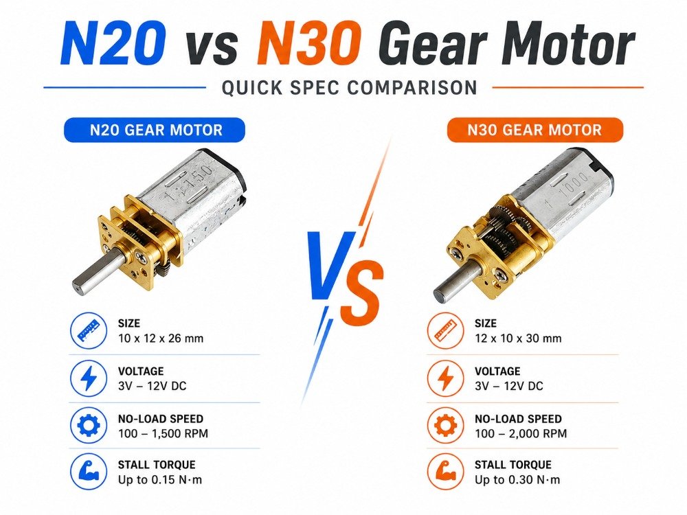
N20 and N30 are commonly used “form factor” labels for micro DC gear motors: shorthand for a family of envelope sizes, gearbox footprints, and output-shaft conventions you’ll see across suppliers. The catch is that these labels aren’t a universal standard—two vendors can ship “N20” motors with different mounting details, shaft variants, and performance curves.
In practice, the difference that matters most is size headroom: N30 is usually the N20-like footprint with a longer motor body, giving more torque/thermal margin at the same voltage (or the same torque at lower current), though details vary by vendor.Pololu forum discussion describing N30 as N20-like but longer
This guide compares the specs that actually drive selection—dimensions, mounting/fit, voltage/current, gear ratio trade-offs, and integration risks—then maps each to typical use cases.
If you need to choose fast, do three checks first:
Torque margin: Do you have enough output torque with stall protection? (Avoid sizing purely by no-load RPM.)
Space + mounting: Do the body length, shaft location, and bracket pattern physically fit your mechanism?
Voltage + driver current: Can your power/driver survive the motor’s stall current and your worst-case duty cycle?
Dimensions & mounting
The labels don’t guarantee cross-vendor mechanical interchangeability, so treat the drawing as the source of truth.
What to compare | N20: typical expectation | N30: typical expectation | Why it matters / what to verify |
|---|---|---|---|
Gearbox face / mounting footprint | Often similar across N20 families | Often similar to N20 families | Don’t assume bracket compatibility—verify hole spacing, datum faces, and any shoulders on the drawing. |
Motor body length | Shorter body in many product lines | Longer body in many product lines | The extra length is the usual “headroom” trade: more power/torque margin, but harder packaging. Use real vendor drawings (e.g., INEED examples: 15 mm vs 20 mm motor body length on worm-gear variants).INEED’s N20 micro worm gear motor specs and INEED’s N30 worm gear motor specs |
Wiring and bend radius | Less rear clearance to route leads | More rear clearance is possible, but depends on connector/encoder | Leave space for a realistic harness bend; “fits in CAD” often fails on the bench. |
Output shaft variants | D-shaft / round / screw / stepped (vendor-dependent) | Same menu of variants (vendor-dependent) | Freeze shaft diameter, usable length, flat depth, chamfer, and coupling method early. If you need customization, request it explicitly.Guide to shaft and connector customization |
Encoder packaging | Possible, but tight on stack-up | Possible; may tolerate encoder stack-up better if length budget exists | Check encoder cap height, whether a rear shaft is required, and connector exit direction. “Electrical choice” becomes a mechanical constraint fast.Encoder selection criteria overview |
Performance & specs (N20 vs N30 gear motor)
Instead of comparing “RPM at X volts,” compare the numbers that drive your electronics, temperature rise, and real speed at load.
Spec / decision point | N20: typical expectation | N30: typical expectation | What to request / verify |
|---|---|---|---|
Rated voltage offerings | Commonly 3 V / 6 V / 12 V windings (varies by vendor) | Same | Voltage alone doesn’t size the driver—pair it with current data. |
Stall current (driver sizing) | Often higher than people expect for the package | Can be similar or higher; depends on winding | Always request stall current (or winding resistance to calculate it). “Same voltage” ≠ same stall current. |
No-load vs loaded point | No-load RPM is easy to quote | Same | Ask for no-load current and a rated loaded point at an agreed torque/speed. Don’t compare quotes using only “RPM + voltage.” |
Gear ratio selection | Wide menus (often ~10:1 to 1000:1 across catalogs) | Same | Pick ratio to hit required speed at load, then validate stall torque/current margin. |
Output speed bands at 6 V (rule-of-thumb) | Low ratio ~10–30:1 → faster; mid ~50–100:1 → balanced; high ~150–300+ → force/holding | Same | Use bands as a first filter, then prototype under real load—actual speed will drop from no-load. |
Torque / thermal headroom | More likely to run near limit in hard loads | Often more margin thanks to longer motor body (varies by model) | If you’re torque-limited, a larger motor (often N30-like) can reduce time spent near stall current. |
Stall / hard-stop protection | Needs explicit protection in many mechanisms | Same | Treat stalls as normal if hard stops exist. Use current limiting or stall detection.Arduino guidance on stall protection |
Noise and temperature drivers | Gear mesh, alignment, mounting resonance; heating mainly duty cycle × current | Same | Plan for enclosure heat; bench tests tend to under-predict. For failure modes, contamination and materials matter over life.Precision Microdrives on gearmotor lifetime |
Selection & applications
Use the tables below as a selection shortcut; then validate with drawings and a load test.
Selection gate | What you decide | If this is true… | Choose / do this |
|---|---|---|---|
Space (mechanical) | Envelope and stack-up | Body length is tight | Start with N20 and lock the drawing early. |
Space (mechanical) | Envelope and stack-up | You can afford extra length and want margin | Shortlist N30 for torque/thermal headroom. |
Electrical (driver) | Voltage and current capability | Stall/jam conditions are possible | Require stall current and implement current limiting / stall detection; size the driver for worst-case duty. |
Functional (speed at load) | Target speed band | You need faster output speed | Try lower ratios (~10–30:1), then validate torque margin. |
Functional (speed at load) | Target speed band | Balanced general-purpose | Try mid ratios (~50–100:1), then validate current/temperature. |
Functional (force/holding) | Torque / holding | You need higher torque / holding | Try higher ratios (~150–300+), but double-check efficiency and stall protection. |
Interfaces | Shaft + encoder packaging | You need closed-loop control | Freeze encoder type, cap height, and connector exit direction before bracket design. |
Typical use case pattern | N20 tends to fit when… | N30 tends to fit when… | |
— | — | — | |
Compact mechanisms | The envelope dominates and loads are moderate | You have the room and want margin against variation and load spikes | |
Encoder builds | You can manage the encoder stack-up in the available space | You need encoder + connector routing space without collisions | |
Variable or heavier loads | You can’t accept extra length | You’d rather avoid living near stall current during spikes or jams | |
Common integration risk | What it looks like in testing | Prevention checklist | |
— | — | — | |
Driver sized to “rated current” only | Brownouts, driver thermal shutdown, MOSFET failures at jams | Size to stall current, limit current in firmware/hardware, test worst-case jams. | |
Duty cycle and enclosure heat ignored | Works on bench, fails in housing at elevated ambient | Measure temperature rise in the real enclosure at worst duty cycle. | |
Mechanical overloading of the shaft | Noise increases, early bearing wear, backlash growth | Reduce radial/axial loads; add external support bearings if needed. | |
Assuming N20/N30 implies bracket interchangeability | Assembly rework, misalignment noise | Require the drawing package and verify datums/hole patterns before PO. | |
Under-specified RFQ interface details | Correct “motor” arrives but won’t integrate | Specify shaft geometry, connector orientation, encoder requirements, and acceptance checks. |
Conclusion
N20 and N30 are best treated as selection starting points, not guaranteed standards. In many product families, N30 buys you extra body length and therefore more torque/thermal headroom, while N20 remains the compact default when envelope dominates.
When to favor each:
Favor N20 when space is tight and your torque requirement is moderate.
Favor N30 when you need margin—variable loads, higher torque demand, or you want to reduce the likelihood of running near stall current.
Next steps are boring but decisive: verify drawings, prototype under real load, and confirm drivers against stall current and duty cycle. If you’re sourcing multiple variants, ask your supplier to confirm which parameters are fixed (envelope, shaft, connector, encoder) and which can be tuned (gear ratio, winding, speed/torque point) so your team isn’t debugging a moving target.
FAQ
1) Are N20 and N30 mechanically interchangeable?
Not reliably. “N20” and “N30” are form-factor labels, not universal standards. Even when the gearbox face looks similar, vendors may change body length, shaft geometry, datum features, and bracket hole patterns. Treat the drawing as the source of truth and verify the full stack-up before you release a PO.
2) What’s the one electrical spec I should always ask for in an RFQ?
Stall current (or winding resistance so you can calculate it). It determines driver sizing, brownout risk, and worst-case heating. Two motors with the same rated voltage can have very different stall currents, so don’t compare quotes using only “RPM + volts.”
3) If I need more torque, should I just choose a higher gear ratio?
Not automatically. A higher ratio can increase available output torque, but it also increases losses and can push you closer to long stall events in hard-stop mechanisms. A common, safer pattern is:
Pick a ratio that meets your required speed at load
Validate stall torque/current margin and thermal limits
If you’re still torque-limited, consider stepping up the motor package (often N30-like) to avoid living near stall current