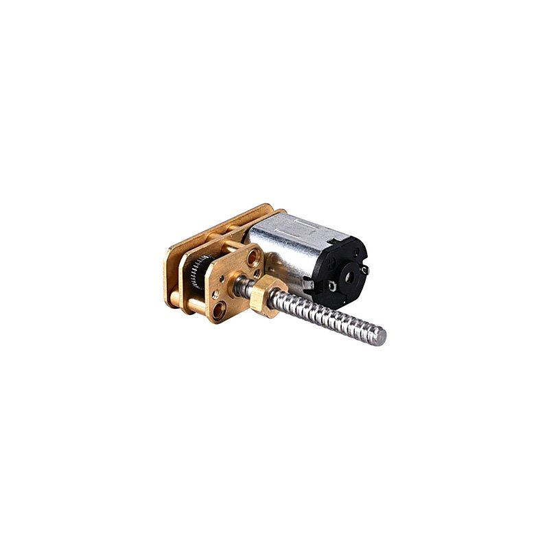
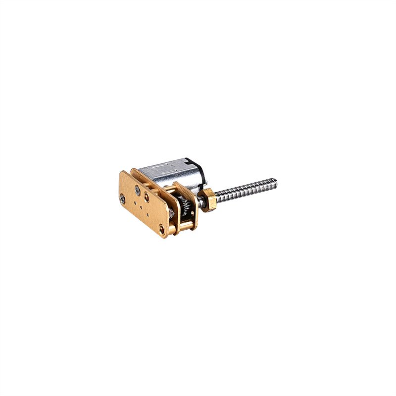
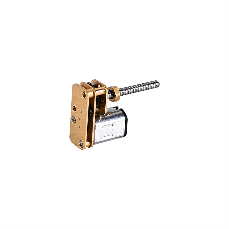
N20 Offset Spur Gear Motor

Overview: 

N20 offset spur gear motor (MPN: IND-24GMN20) is an offset (parallel-shaft) spur gear motor designed for compact assemblies where a standard in-line gear motor may cause packaging conflicts.
Its offset shaft layout helps avoid interference with brackets, ribs, and housings, and enables easy alignment of gears or linkages without adding an extra idler gear.

Before finalizing your design, please also confirm the U‑shape N20 gearbox dimensions, including gearbox profile, shaft position, and available mounting space.

Key Checks Before You Choose (and Before Mass Production)


1. Voltage: confirm your available supply (2.5V / 5V / 12V)
2. Gear ratio: select 3:1–750:1 based on required speed and torque
3. Gearbox length: confirm the gearbox length is 24.0 mm during mechanical design
4. Torque requirement: higher gear ratio = higher peak torque capability
5. Driver capability: ensure your controller/driver can support the motor current
6. Real load testing (recommended): test under real conditions for speed, current, torque, noise, temperature, and lifetime to ensure safe and stable operation
If you tell me your load, target RPM, and supply voltage, I can suggest a short list of the best gear ratios for IND-24GMN20.

Still deciding whether N20 is enough margin or you should step up in body length? Use our N20 vs N30 gear motor spec guide to compare torque headroom, driver sizing, and integration risks before you release a PO.

Outline drawing


Customizable items: 1. Length and shape of the shaft; 2. Voltage, output speed, torque, etc. ; 3. Adding connectors, lead wires; 4. Adding gears to shaft; 5. Adding encoder.


Voltage Selection Guide

Low-voltage products: Select 2.5V or 5V based on the power supply
12V systems: If a higher operating voltage is required, choose the 12V version


The basic parameters are for reference


Ratio MPN Voltage No Load On Load Stall
Operating                                  Range (V) Rated Voltage(V) Current (mA) Speed                  (rpm) Current (mA) Speed                       (rpm) Torque                    (g.cm) Current (mA) Torque                    (g.cm)
50 IND-24GMN20-50 2.0-3.0 2.5 60 200 85 120 75 500 420
100 IND-24GMN20-100 3.0-8.0 5 40 120 80 72 150 520 1000
298 IND-24GMN20-298 8.0-11.0 9 40 65 80 40 168 650 4100
500 IND-24GMN20-500 10.0-14.0 12 40 44 80 26 185 800 7800

Notes: These specs are samples. Please contact us to customize your parameters.

Gearbox sheet

Gear box length/L(mm) Gear Ratios
24 1/3 1/10 1/20 1/50 1/63 1/70 1/100
1/110 1/150 1/210 1/250 1/298 1/380 1/500 1/750


Gear Ratio Selection Guide (Speed vs. Torque)

For higher speed: choose a lower gear ratio, such as 1:3, 1:63, or 1:150
For balanced output (speed and torque): choose 1:210, 1:250, 1:298, or 1:380
For higher torque: choose 1: 750 (for heavy loads and stronger torque margin)
(Typical selection range: 1:3 to 1:750 depending on your needs.)


FAQ for N20 Offset Spur Gear Motor (IND-24GMN20)


Q1. What is an offset shaft gear motor, and why choose it over inline?

Offset output shifts the shaft centerline away from the motor centerline, improving clearance and alignment in tight housings. It often avoids bracket redesign or extra idler gears.

Q2. What is the operating voltage range? Can I run it on 3V / 5V / 6V / 12V?

The platform supports 2–14V, but the correct winding and ratio depend on your target loaded RPM/torque and driver limits. Share your supply voltage and duty cycle and we will recommend a safe configuration.

Q3. How do I choose the gear ratio (50:1 / 100:1 / 298:1 / 500:1)?

Gear ratio is mainly a trade-off between speed and torque:

  • Higher ratio (e.g., 298:1, 500:1) → lower output RPM, higher output torque/holding capability; better for load spikes and hard-stops (common in smart locks and actuators).
  • Lower ratio (e.g., 3:1, 100:1) → higher output RPM; better when speed is more important than torque.
    If you share your target RPM and estimated load torque, you can narrow down the ratio quickly.

Q4. How do I prevent damage from stall or hard-stop conditions (common in locks/actuators)?

Stall (locked rotor) can cause high current and heat in micro DC gearmotors. Recommended protections include:
  • Use a driver/control strategy with current limiting and stall detection (current threshold or time threshold).
  • Design with torque margin and avoid long-duration stall.
  • If you need feedback, consider a version with an encoder for motion/position monitoring and abnormal-stop detection.

Motor Customization Guide

Please provide your detailed requirements, and our engineers will offer you the optimal solution tailored to your specific application.

Contact Us

You need our support, and we are ready to provide assistance.

Motor products pose complexities in understanding, specifying, and integrating, with no industry standards. We offer expertise to mitigate design, manufacturing, and supply risks.

Contact our team now.

You can easily upload your 2D/3D CAD design files, and our sales engineering team will provide you with a quote within 8 hours.

Motors Catalog Download

Download and view the full series catalog for free

Contact Us

You need our support, and we are ready to provide assistance.

You can easily upload your 2D/3D CAD design files, and our sales engineering team will provide you with a quote within 24 hours.

Contact Us

You need our support, and we are ready to provide assistance.

Motor products pose complexities in understanding, specifying, and integrating, with no industry standards. We offer expertise to mitigate design, manufacturing, and supply risks.

Contact our team now.

You can easily upload your 2D/3D CAD design files, and our sales engineering team will provide you with a quote within 24 hours.