Introduction
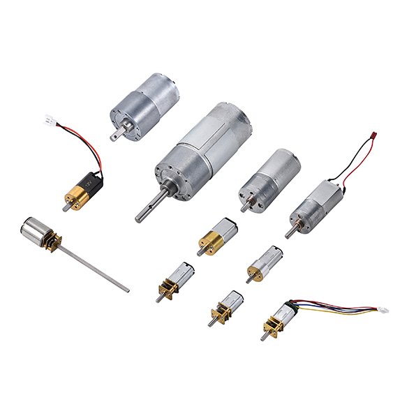
This primer is for OEM teams who need to spec and qualify micro brushed DC motors (typically ≤16 mm diameter) without turning the integration into a science project. You’ll learn what commutation is, how torque and speed relate, and what tends to break—or fail EMC—in real assemblies.
The goal is practical: translate an application into first‑pass motor and driver requirements, then plan validation (thermal, life, and EMC) before late-stage surprises. The focus is small form-factor brushed DC motors used inside OEM products, where packaging, wiring, and compliance constraints can matter as much as the motor itself.
A quick note on size: larger brushed DC motors (>16 mm) often have more room for terminals, suppression parts, and heat sinking—and they may tolerate abuse a bit better. Micro motors are less forgiving: resistance is higher, thermal mass is lower, and small harness/layout choices can dominate performance and EMI.
How brushed DC motors work
Components and commutation
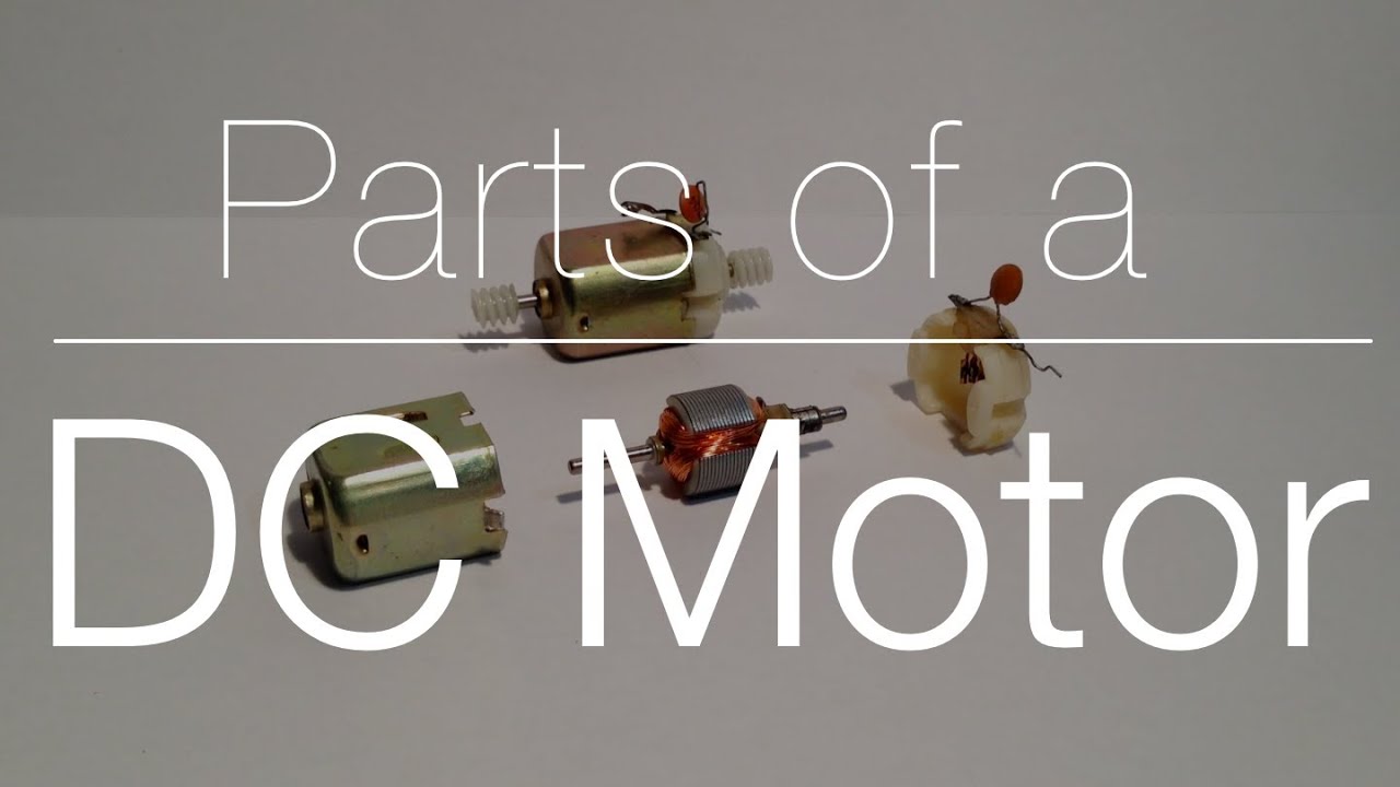
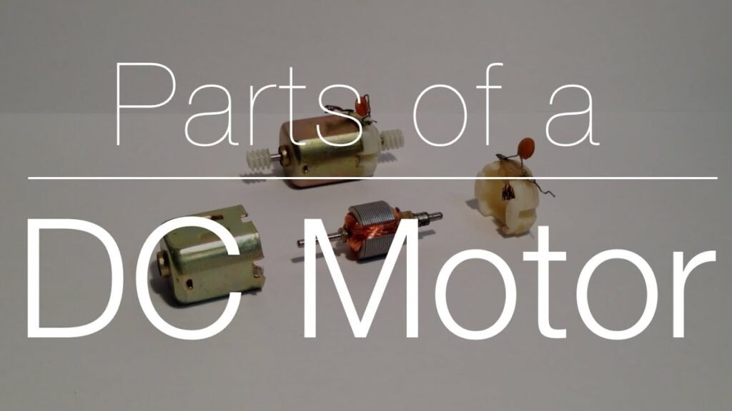
A brushed DC motor uses a mechanical commutator. Instead of electronics switching phases, a segmented commutator and brushes reverse current in the armature coils as the rotor turns.
At a high level you have:
Stator field (often permanent magnets) that provides magnetic flux.
Armature (rotor) windings that carry current and create torque.
Commutator segments connected to individual armature coils.
Brushes that ride on the commutator and energize the right coil at the right time.
This switching moment is also where many real-world problems start. When a brush transitions between commutator segments, the winding inductance can generate voltage spikes and arcing. In micro motors, that energy couples into your wiring more easily—so EMI suppression and harness routing usually need to be designed in, not added later.
Torque, back‑EMF, and speed
Most “will this motor work?” questions come down to two simple relationships:
Torque is proportional to current: more current gives more torque via the torque constant Kt (Motion Control Tips: current vs torque).
Back‑EMF is proportional to speed: as the rotor spins faster, it generates a counter-voltage that reduces current (Northwestern Mechatronics Wiki: brushed DC motor theory).
A common steady-state model is:
Voltage balance: V ≈ I·R + Ke*·ω*
Torque: T ≈ Kt*·I*
In SI units, Kt and Ke are often numerically equal; some datasheets instead use the speed constant Kv in RPM/V (the inverse form). FAULHABER’s tutorial is a practical reference for how these constants show up in calculations and datasheets (FAULHABER: motor calculations and parameters).
So what: voltage mostly sets the no-load speed. Your current limit (driver + battery/supply) sets the available torque—and your heat margin.
⚠️ Warning: Stall is only OK when you have a defined time limit and a current/thermal limit. Otherwise, stall current (V/R) can exceed what the winding and driver can tolerate.
Core variants and use cases
Even within “micro brushed DC motor,” design choices change behavior in ways that matter to product planning:
Iron-core vs. coreless (where available): coreless designs can reduce inertia and cogging, which helps fast response and low vibration—but they can change thermal behavior and driver expectations.
Bearing and brush system: bushing vs. ball bearing and brush material drive noise, life, and commutation behavior.
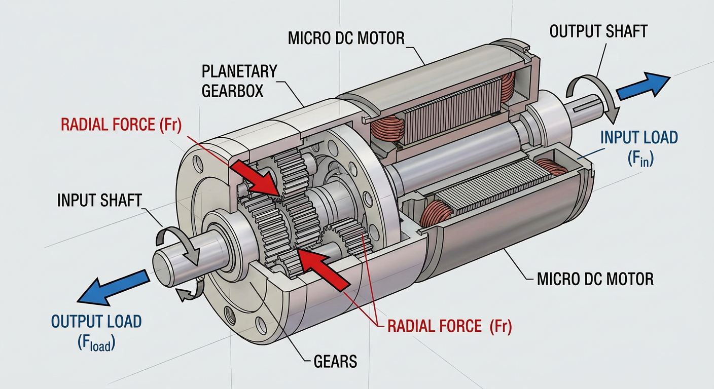
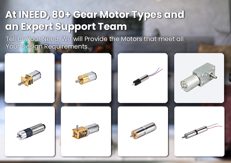
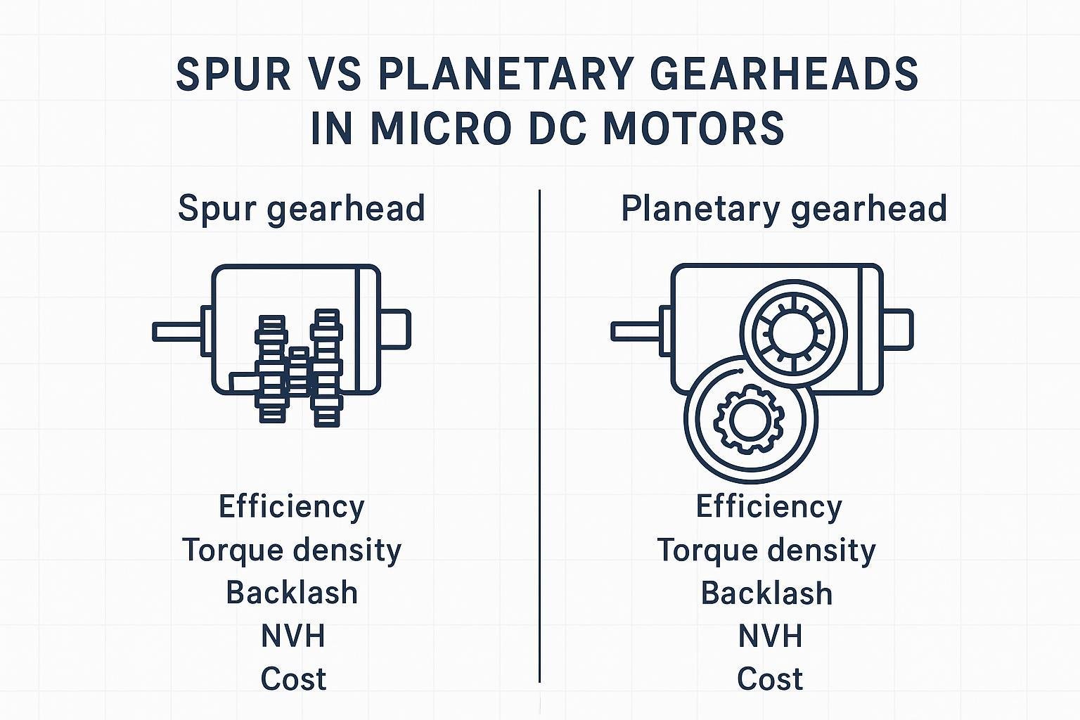
Integrated gearbox: many products care more about output torque/speed at the load than raw motor RPM, which pushes the decision toward gearmotors.
Micro brushed motors are common in compact actuations, small pumps/valves, intermittent motion, and mechanisms where simple control is preferred and some brush wear is acceptable.
Selection and control
Torque–speed and sizing
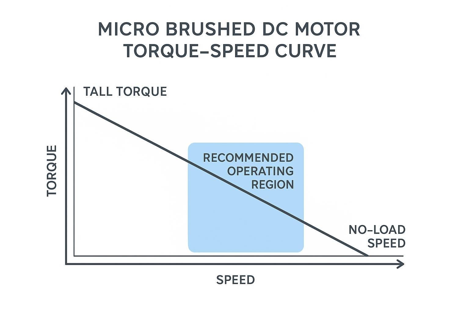
A brushed DC motor’s torque–speed curve is often close to linear at a fixed supply voltage. It runs from stall torque at zero speed to no-load speed at near-zero torque, as summarized in ROHM’s overview of brushed motor characteristics (ROHM: characteristics of brushed DC motors).
Three practical sizing steps help avoid obvious misses:
Start at the load, not the motor: estimate required output torque vs speed over the duty cycle (including peaks, friction growth, and worst-case supply).
Translate to motor torque/speed using the gearbox ratio and efficiency (if geared), then leave headroom for tolerance stack and wear.
Check current and heat early: torque implies current (T ≈ Kt*·I*). Your driver’s current limit and your thermal path (winding → housing → ambient) usually decide whether the “right” motor is actually viable.
A conservative first pass is to operate away from stall and avoid living at very low speeds with high torque unless the duty cycle is clearly intermittent.
PWM, H‑bridge, and protection
PWM speed control works because the motor’s electrical and mechanical inertia tends to average the applied voltage over each cycle. In practice:
PWM duty cycle controls average applied voltage, which shifts the effective no-load speed.
Load torque sets the needed current; if you cap current, you cap torque.
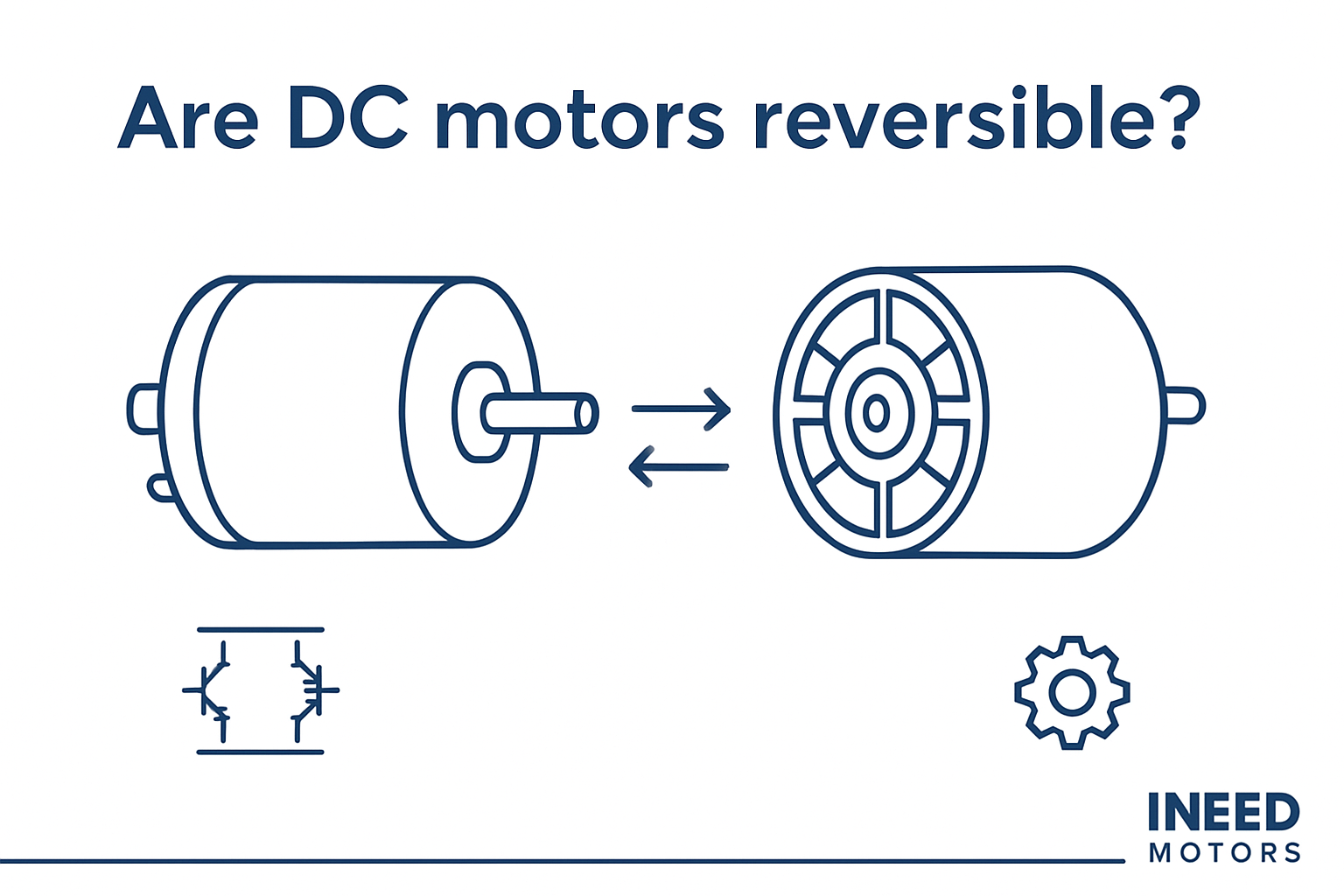
For bidirectional motion, a DC motor is typically driven by an H‑bridge. Protection features that matter in OEM builds:
Current limiting (cycle-by-cycle or averaged) to control stall and transient events.
Flyback paths for inductive current during switching (diode/body-diode and MOSFET strategy).
Undervoltage/overvoltage behavior (brownout can create repeated stall/ restart cycles).
Thermal sensing (motor or board) when duty cycles vary across SKUs.
Where feasible, it’s worth correlating control settings to measurable outputs: in test, log supply voltage, PWM duty, current, speed (if available), and case temperature. That dataset becomes your quickest way to diagnose field edge cases.
Gearboxes, duty, and thermal limits
Gearboxes solve one problem and create another:
They let the motor run at a more efficient operating speed while delivering usable output torque.
They add losses (heat), backlash, and sometimes acoustic noise.
Thermal limits are typically the silent constraint. Two motors that look similar on a torque–speed plot can behave very differently once mounted into a plastic enclosure with limited airflow.
A useful habit is to define duty explicitly:
time at load
time at stall (if any)
ambient temperature range
allowable temperature rise (winding, case, surrounding materials)
If you want a selection checklist format, INEED Motors maintains a practical internal reference you can cross-check against your own requirements: the DC Brushed Motor Selection Guide.
Reliability, noise, and EMI
Wear, arcing, and life drivers
Brushed motor life is usually driven by wear mechanisms and commutation conditions:
Brush wear depends on brush material, spring force, surface speed, contamination, and duty.
Commutator condition (film formation, roughness, eccentricity) affects arcing and noise.
Load profile matters: frequent starts, reversals, and stall events increase current peaks and brush stress.
If a design is marginal, the symptom is often not immediate failure—it’s drift: higher current, higher noise, and a growing spread in performance across units.
Suppression: caps, snubbers, ferrites
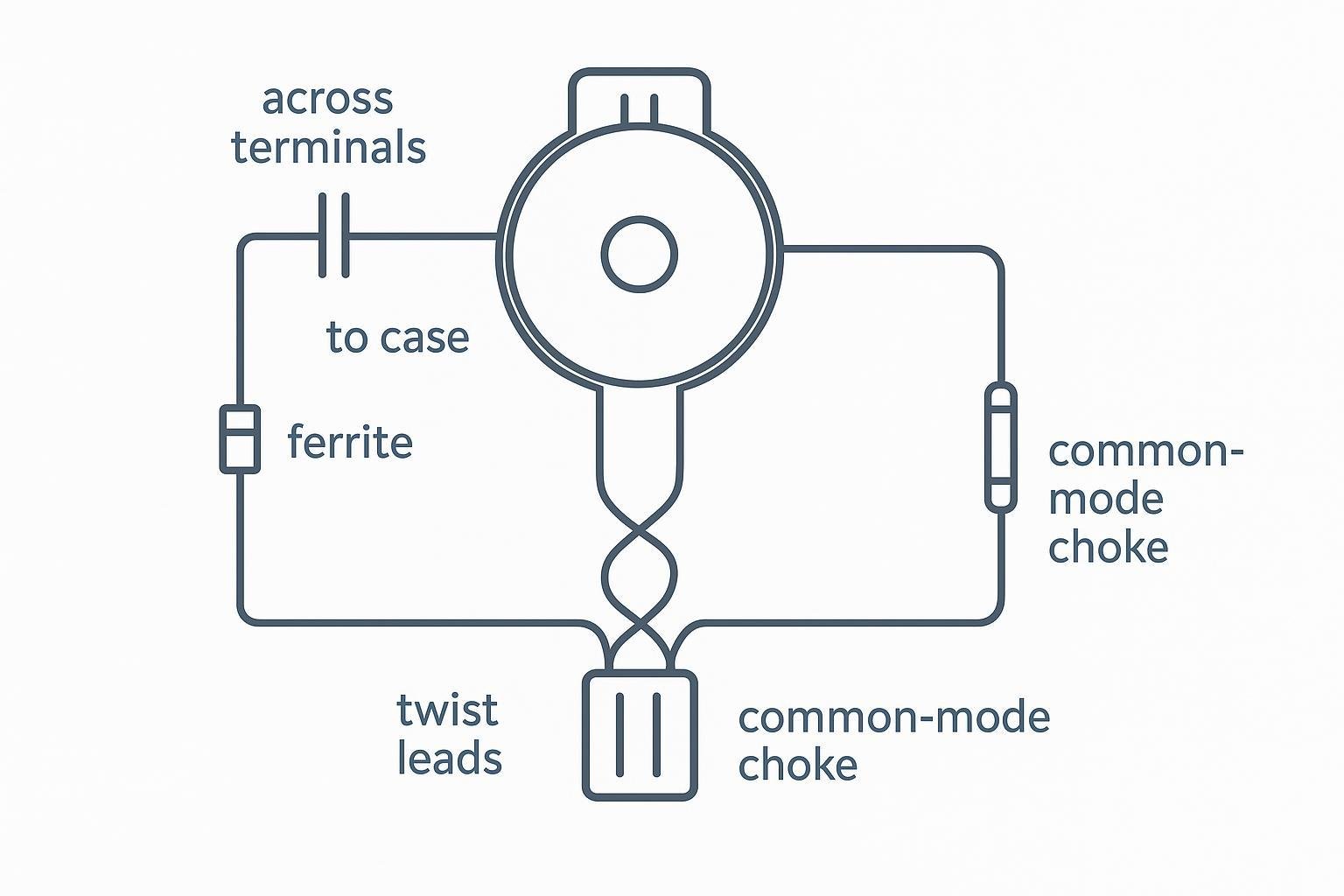
Brush arcing is a common EMI source in brushed motors, as noted in Portescap’s EMC discussion (Portescap: DC motors with EMC considerations). The mitigation strategy is typically layered:
Suppress at the source (motor terminals / brush card) before noise gets onto the harness.
Filter conducted emissions (differential-mode and, when needed, common-mode).
A common baseline network is a small ceramic capacitor across the motor terminals; in tougher environments, add additional capacitors to the case, ferrite beads, or a common-mode choke depending on whether the dominant issue is differential or common-mode coupling.
Placement is not optional. Johanson Dielectrics’ guidance on motor EMI filtering emphasizes keeping traces short/wide and routing the power leads “through” the suppression elements so noise can’t bypass them (Johanson Dielectrics: EMI DC motor filtering basics).
Layout, harness, and grounding
For OEM integration, harness and grounding decisions often dominate the EMI outcome:
Minimize loop area: keep motor current loops tight; twist motor leads where possible.
Separate sensitive circuits: don’t bundle motor leads with sensor, RF, or high-impedance analog lines.
Control return paths: avoid “mystery grounds” through mounting hardware; define chassis vs signal ground intentionally.
Shielding is a system choice: it can help, but only if termination is planned (and verified in EMC test).
INEED Motors’ engineering team can review your load profile, driver limits, and mechanical interfaces to suggest winding/brush options and minor customizations (shaft, terminals, suppression parts) to reduce validation iterations.
Compliance and procurement
RoHS/REACH documentation
If you ship into the EU, treat material compliance as an evidence package, not a checkbox.
Typical requests include a RoHS declaration of conformity and REACH statements covering SVHC presence against a specific Candidate List revision; practical guidance on the documentation set and adjacent requirements (including SCIP implications) is summarized in Accuris Tech’s REACH/RoHS/SCIP overview (2024).
For REACH specifically, buyers often ask for an SVHC declaration that states whether any SVHC exceeds the 0.1% w/w threshold and which Candidate List version was used, as described in GlobX’s REACH compliance note (2026).
QA, test reports, and traceability
For motors and motorized subassemblies, procurement teams commonly want traceability that lets a test report map back to a build lot:
Incoming material declarations for high-risk materials (e.g., plating, soldered terminations)
Lot/batch IDs on motor builds and key subcomponents
Performance verification (e.g., speed/torque/current under defined conditions)
Records of final inspection and any burn-in or life test sampling
Cofactr’s RoHS/REACH buyer guidance is a useful reminder that manufacturers must be able to prove compliance using a mix of supplier declarations and testing evidence—not just assert it (Cofactr: RoHS 3 & REACH for electronics buyers).
Supplier capability and lead times
Capability and lead time risk show up late if you don’t ask early. Two procurement questions that save time:
Can the supplier maintain a stable process window (commutation quality, brush material, winding resistance tolerance) across lots?
Can the supplier provide the exact evidence package your compliance process requires for your region and end market?
In many programs, the fastest path to schedule certainty is to align on test conditions, documentation scope, and any customization/NRE items before EVT builds.
Conclusion
A brushed DC motor is simple to drive, but not always simple to qualify. The governing relationships—torque ↔ current and back‑EMF ↔ speed—let you translate load requirements into first-pass electrical and thermal constraints. The practical risk areas tend to be stall/overload heating, brush wear over the duty profile, and EMI coupling through the harness.
A first-pass spec checklist for an OEM build:
Supply range and allowed brownout behavior
Required torque/speed at the load across duty cycle (including peaks)
Gear ratio and efficiency assumptions (if geared)
Current limit strategy and driver protection features
Thermal path assumptions and temperature limits
EMI suppression topology and placement plan
RoHS/REACH/SVHC documentation scope and traceability expectations
Next steps are straightforward: prototype with instrumentation (current, speed, temperature), validate the duty cycle under worst-case conditions, then run pre-compliance EMC testing early enough that suppression and harness changes are still cheap.
FAQ
1) What should I look at first when choosing a micro brushed DC motor?
Start with three inputs: required torque at the load, duty cycle (how long it runs, starts, reverses, or stalls), and your available supply/driver current limit. In micro motors, current quickly turns into heat, so a motor that “meets torque” on paper can still fail in a tight enclosure.
2) Is stall ever OK for a micro brushed DC motor?
Yes—but only when stall is time-limited and you have a defined current limit (or thermal cutoff). Micro motors have less thermal mass, so repeated stall/restart events can cook windings or erode brushes fast.
3) What are the simplest steps to reduce EMI from a brushed motor?
Use a layered approach: add a small capacitor across the motor terminals, keep leads short and twisted to reduce loop area, and place suppression parts at the motor (before noise gets onto the harness). If problems persist, add ferrites or a common-mode choke based on what your EMC test shows.