Introduction
During micro DC gear motor selection, mechanical engineering teams routinely focus on speed, nominal torque, operating voltage, and physical envelope. However, shaft radial force—the side load applied perpendicular to the shaft centerline—often gets overlooked until physical prototype testing or early field deployments reveal unexpected component degradation.
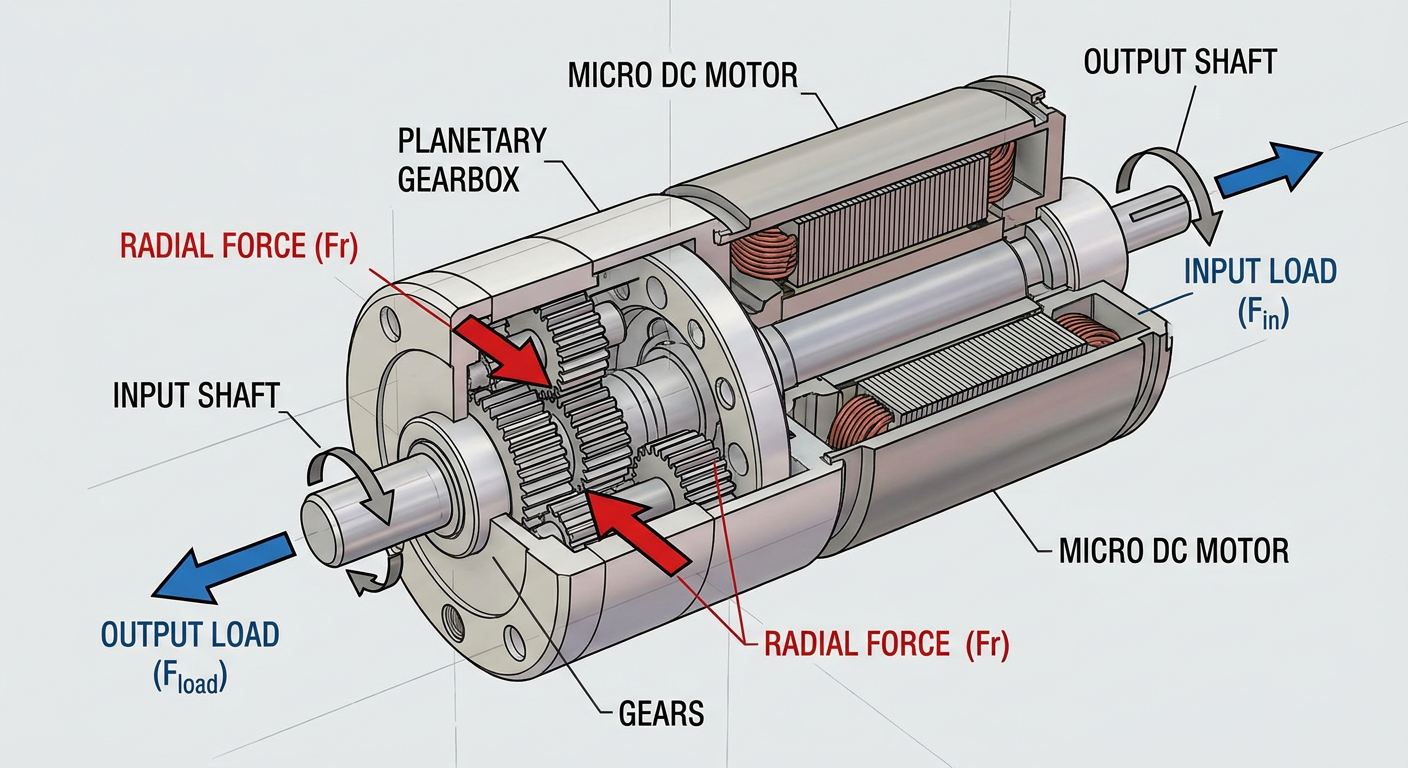
When an external drive element such as a spur gear, timing belt pulley, chain sprocket, or drive wheel mounts directly to a gear motor shaft, it generates a continuous mechanical side load. In addition to external drive attachments, internal gear meshing forces within multi-stage gearboxes generate internal radial loads that react directly against the shaft support bearings.
Understanding how radial forces act across both input and output shafts prevents catastrophic engineering oversights:
Root Cause Prevention: Learn how radial loads originate at the gear mesh and scale through reduction stages.
Datasheet Verification: Interpret FR1 (input) and FR2 (output) permissible radial load ratings accurately.
Reliability Assurance: Prevent premature bearing fatigue, shaft bending, tooth misalignment, and elevated noise, vibration, and harshness (NVH).
Key Takeaway: Torque transmits power through tangential force, but gear pressure angles convert a significant portion of that force into radial side load. Ignoring radial load ratings risks bearing spalling and shaft deflection long before reaching thermal or electrical torque limits.
What Is Radial Force in Gear Motors?
The Difference Between Radial and Tangential Force
To analyze gear motor dynamics, mechanical engineers divide total gear mesh contact forces into perpendicular components:
Tangential Force (Ft): The driving force component acting tangentially to the pitch circle. Tangential force performs useful work by transmitting mechanical torque from the driving pinion to the driven gear.
Radial Force (Fr): The separating force acting perpendicular to the shaft’s rotational axis, directed toward the shaft center. Radial force performs no useful rotational work; instead, it pushes mating gear teeth apart and loads the supporting bearings and motor casing.
While tangential force drives the rotation, radial force acts as an overhung or internal bending load on the shaft.
Force Component | Vector Direction | Primary Function | System Impact |
|---|---|---|---|
Tangential Force (Ft) | Parallel to pitch circle tangent | Transmits torque and mechanical power | Determines output torque capacity |
Radial Force (Fr) | Perpendicular to shaft axis (radially inward/outward) | Separates mating gears | Generates bearing radial load and shaft bending moment |
The Governing Formula: Fr = Ft × tan(α)
The magnitude of radial force depends directly on tangential force and the gear tooth pressure angle (α). For standard spur and planetary gears, the fundamental relationship is expressed as:
Fr = Ft × tan(α)
Where:
Ft = Tangential force in Newtons (N), derived from torque T (in N·m) and gear pitch radius r (in meters):
Ft = T / rorFt = (2 × T) / d(where d is pitch diameter in meters).α = Involute gear pressure angle (typically 20° in industrial micro gearboxes).
Fr = Resulting radial separating force in Newtons (N).
For a standard 20° pressure angle gear mesh: tan(20°) ≈ 0.364
This means that for every 100 N of tangential driving force, the gear mesh generates approximately 36.4 N of radial side force pushing directly against the shaft and bearings.
Why Manufacturers Specify Separate Limits for Input and Output Shafts
A complete gear motor comprises two distinct mechanical zones: the high-speed motor input shaft (or primary sun pinion) and the low-speed gearbox output shaft. Manufacturers specify separate permissible radial load ratings—designated FR1 for input shafts and FR2 for output shafts—because these two locations operate under fundamentally different mechanical conditions:
Shaft Diameter and Geometry: Input motor shafts are typically slender (e.g., 1.0 mm to 3.0 mm diameter) designed for high rotational speed and low inertia, whereas output shafts are thicker (e.g., 3.0 mm to 8.0 mm diameter) to handle multiplied output torque.
Bearing Types and Spacing: Input shafts rely on small precision ball bearings or sintered bronze sleeve bushings optimized for high RPM (e.g., 5,000 to 15,000 RPM). Output shafts utilize larger ball bearings, needle roller bearings, or dual-spaced bushings engineered for high static and dynamic side loads at lower speeds (e.g., 10 to 500 RPM).
Overhung Distance: Output shafts often extend outside the gearbox housing to mount external drive sprockets or pulleys, creating a lever arm (overhang distance) that amplifies shaft bending moments.
Primary vs. Secondary Gear Stage Radial Force
How Torque Multiplication Scales Radial Force Through Reduction Stages
In a multi-stage gear motor (such as a multi-stage planetary or spur gearbox), speed decreases while torque multiplies proportionally by the gear ratio (i) and mechanical efficiency (η):
T_stage2 = T_stage1 × i × η
Because tangential force Ft is proportional to torque (Ft = 2 × T / d), tangential force increases dramatically at each successive reduction stage. Consequently, internal radial forces (Fr = Ft × tan(α)) expand at every stage from the primary (input) stage to the secondary (output) stage.
Primary (Input) Stage: Operates at high speed and very low torque. Internal radial forces on the primary pinion are relatively small in magnitude, but high rotational speed accelerates bearing stress cycles per unit time.
Secondary / Final (Output) Stage: Operates at lower speed but handles full multiplied torque. Internal gear meshing forces reach maximum levels here, creating heavy radial loads on the planet carrier bearings and output shaft supports.
Reading FR1 and FR2 Ratings on a Datasheet
When reviewing a gear motor engineering specification datasheet, radial load limits are listed under mechanical limits:
FR1 (Input Shaft Permissible Radial Load): The maximum allowable radial side load applied at the midpoint of the input shaft extension. This value is critical when an external encoder gear, motor pinion, or coupling connects to the rear motor shaft or input pinion.
FR2 (Output Shaft Permissible Radial Load): The maximum allowable radial force applied at a specified distance (typically the midpoint, e.g., 5 mm or 10 mm from the front mounting flange) on the output shaft extension.
Pro Tip: FR2 values on datasheets are defined at a specific reference distance from the housing face. If your pulley or gear mounts further out on the shaft, the allowable radial load decreases proportionally due to the increased bending moment arm.
Real-World Example: A Two-Stage Planetary Gearbox
Consider a 16 mm micro DC gear motor with a 25:1 two-stage planetary reduction gearbox:
Input Motor Shaft:
Speed: 10,000 RPM
Input Torque (T1): 0.5 mN·m (0.0005 N·m)
Sun Pinion Pitch Diameter (d1): 3.0 mm (0.003 m)
Tangential Force:
Ft1 = (2 × 0.0005) / 0.003 = 0.333 NInternal Radial Force:
Fr1 = 0.333 × tan(20°) = 0.121 NDatasheet FR1 Rating: 2.0 N (Operating safely within limits).
Output Gearbox Shaft:
Speed: 400 RPM
Output Torque (T2): 100 mN·m (0.100 N·m) (accounting for 80% stage efficiency)
Output Gear / Pulley Pitch Diameter (d2): 10.0 mm (0.010 m)
External Tangential Force:
Ft2 = (2 × 0.100) / 0.010 = 20.0 NExternal Radial Load:
Fr2 = 20.0 × tan(20°) = 7.28 NIf a timing belt pulley is used instead of a gear, belt tension factors (typically 1.5× to 2.5×) increase the external radial load to 15.0 N – 25.0 N.
Datasheet FR2 Rating: 15.0 N at 5 mm overhang. (If belt tension exceeds 15.0 N, additional support or bearing upgrades are required).
Engineering Implications of Exceeding Radial Force Limits
Exceeding specified FR1 or FR2 limits causes severe mechanical degradation across three primary domains:
Excessive Radial Load
► Bearing Fatigue (L10 Life Drops by Power Law) ► Shaft Deflection ► Gear Tooth Tilting & Edge Loading ► NVH Escalation (Vibration, Friction & Acoustic Noise)
Bearing Load and Service Life (MTBF)
Rolling element bearing service life is governed by the ISO 281 basic fatigue rating life formula (L10):
L10 = (C / P)^p
Where:
L10 = Rating life in millions of revolutions (where 90% of a bearing group survives without fatigue spalling).
C = Basic dynamic radial load rating of the bearing (N).
P = Equivalent dynamic radial load applied to the bearing (N).
p = Life exponent (p = 3 for ball bearings, p = 10/3 for roller bearings).
Because bearing fatigue life follows a cubic power law for ball bearings, doubling the applied radial force (P) reduces bearing fatigue life to 1/8th (12.5%) of its original value. Mean Time Between Failures (MTBF) drops drastically, resulting in premature bearing race spalling, elevated running friction, and sudden lockup.
Shaft Deflection and Gear Mesh Misalignment
When external or internal radial loads exceed shaft structural capacity, the shaft acts as a cantilevered beam and undergoes elastic bending deflection (δ):
δ = (F × L³) / (3 × E × I)
Where F is radial force, L is overhang length, E is modulus of elasticity, and I is shaft area moment of inertia (I = π × d⁴ / 64).
Shaft bending introduces two severe secondary issues:
Angular Misalignment: The shaft tilts relative to the internal housing bore, placing severe edge loads on internal support bearings.
Gear Mesh Tilting: In planetary and spur stages, shaft deflection tilts mating gear teeth out of parallel alignment. Instead of distributing load evenly across the entire face width, force concentrates on tooth corners (edge loading), accelerating gear tooth wear and risking tooth root fracture.
Noise, Vibration, and Harshness (NVH) Effects
Before hard mechanical seizure occurs, excessive radial force manifests as elevated NVH:
Vibration Peak Signature: Misaligned gear meshing generates high-frequency order spikes at gear mesh frequency (GMF).
Acoustic Noise: As shaft deflection breaks down lubricating oil films between gear teeth and bearing raceways, metal-to-metal contact produces high-pitched whine and rattling.
Thermal Runaway: Friction spikes at overloaded bearing journals cause localized heating, leading to lubricant degradation and thermal expansion tight spots.
How to Verify Your Application Stays Within Radial Force Limits
To ensure long-term BOM reliability, engineering teams should follow a structured verification process during component selection:
Identify Every External Radial Load Source:
For Spur / Helical Gears: Calculate radial force using
Fr = Ft × tan(α).For Timing Belts / V-Belts: Calculate belt pull using
Fr = (2000 × T / d) × k, where k is the belt pretension factor (1.5 for timing belts, 2.0–2.5 for V-belts).For Sprockets / Chains: Use pretension factor
k ≈ 1.0 to 1.25.For Direct Overhung Mass: Include gravity side loads or centrifugal loads in mobile robotics.
Build a Free-Body Diagram and Calculate Bearing Reactions:
Treat the shaft as a beam supported by two bearings (A and B) with overhung load applied at distance L from the front bearing.
Solve static equilibrium equations (
ΣM = 0andΣF = 0) to determine reaction forces on individual internal bearings.
Compare Calculated Loads Against FR1 and FR2 Datasheet Values:
Verify that input shaft side loads stay below FR1.
Verify that output shaft side loads (adjusted for actual overhang distance) stay below FR2.
Apply a 1.5×–2× Safety Margin for Shock and Misalignment:
Incorporate a dynamic service factor (1.5× for uniform load, 2.0× or higher for shock loads, frequent reversals, or thermal expansion alignment shifts).
When in Doubt, Work with an Engineering Supplier That Provides Detailed Support:
Select a manufacturing partner capable of providing validated radial load curves, 2D/3D CAD models, and customized shaft/bearing options.
Engineering suppliers like INEED Motors offer specialized R&D application verification, custom shaft modifications (D-cuts, keyways, stepped diameters, hardened stainless steel), and integrated ball bearing options to absorb high radial loads in demanding OEM medical, robotics, and industrial applications. Exploring dedicated custom options via INEED Motors planetary gear motors allows engineering teams to resolve overhung load challenges early in the DFM phase.
Conclusion
Stage-Dependent Behavior: Radial force acts as a separating force derived from tangential torque (
Fr = Ft × tan(α)). Because torque multiplies across reduction stages, output shafts experience vastly higher radial loads than input shafts.Dual Verification (FR1 & FR2): Reliable electromechanical design requires verifying both the high-speed input shaft rating (FR1) and the high-torque output shaft rating (FR2) against actual application mechanics.
Proactive Risk Reduction: Investing time during early design phases to calculate radial loads, account for overhang leverage, and consult engineering suppliers saves thousands of dollars in prototype failures, warranty claims, and redesign cycles.
Frequently Asked Questions (FAQ)
How do I calculate allowable radial force if my gear or pulley is mounted further out on the output shaft?
When an external drive component is mounted further from the mounting flange than the standard datasheet reference distance ($L_{ref}$), the allowable radial load ($F_{R2_allowable}$) decreases due to the increased moment arm. You can calculate the adjusted allowable radial force using the formula:
$$F_{R2_adjusted} = F_{R2_rated} times frac{a + L_{ref}}{a + L_{actual}}$$
Where $a$ is an internal bearing distance constant specified by the manufacturer, $L_{ref}$ is the reference distance from the datasheet, and $L_{actual}$ is your actual overhang position.
What is the typical difference between FR1 (input) and FR2 (output) radial load ratings?
FR1 rates the permissible side load on the high-speed input motor shaft, which features smaller shaft diameters and high-RPM precision bearings optimized for low torque. FR2 rates the permissible radial load on the low-speed output shaft, which utilizes larger shaft diameters and heavy-duty ball or needle bearings engineered to withstand high torque multiplication and external drive belt/gear side loads.
How can I prevent premature bearing failure when my application exceeds standard radial load ratings?
If your calculated radial force exceeds datasheet FR2 limits, consider the following engineering solutions:
Reduce Overhang Distance: Shift drive pulleys or gears as close to the mounting flange face as possible to shorten the lever arm.
Use an External Pillow Block Bearing: Support the outer end of the shaft with a secondary external bearing to eliminate cantilever loads.
Upgrade Bearing Configurations: Work with custom motor suppliers like INEED Motors to request dual ball bearings or hardened shaft options designed for high radial load capacity.