Introduction
If you’re specifying a micro DC motor for an OEM product, the hardest part usually isn’t finding a motor—it’s defining a spec that survives EVT/DVT without thermal surprises, noisy gear trains, or controller/encoder mismatches.
This micro DC motor selection guide is written for engineers who need to go from application requirements to a defensible motor + gearbox + feedback stack.
Here’s what you’ll learn:
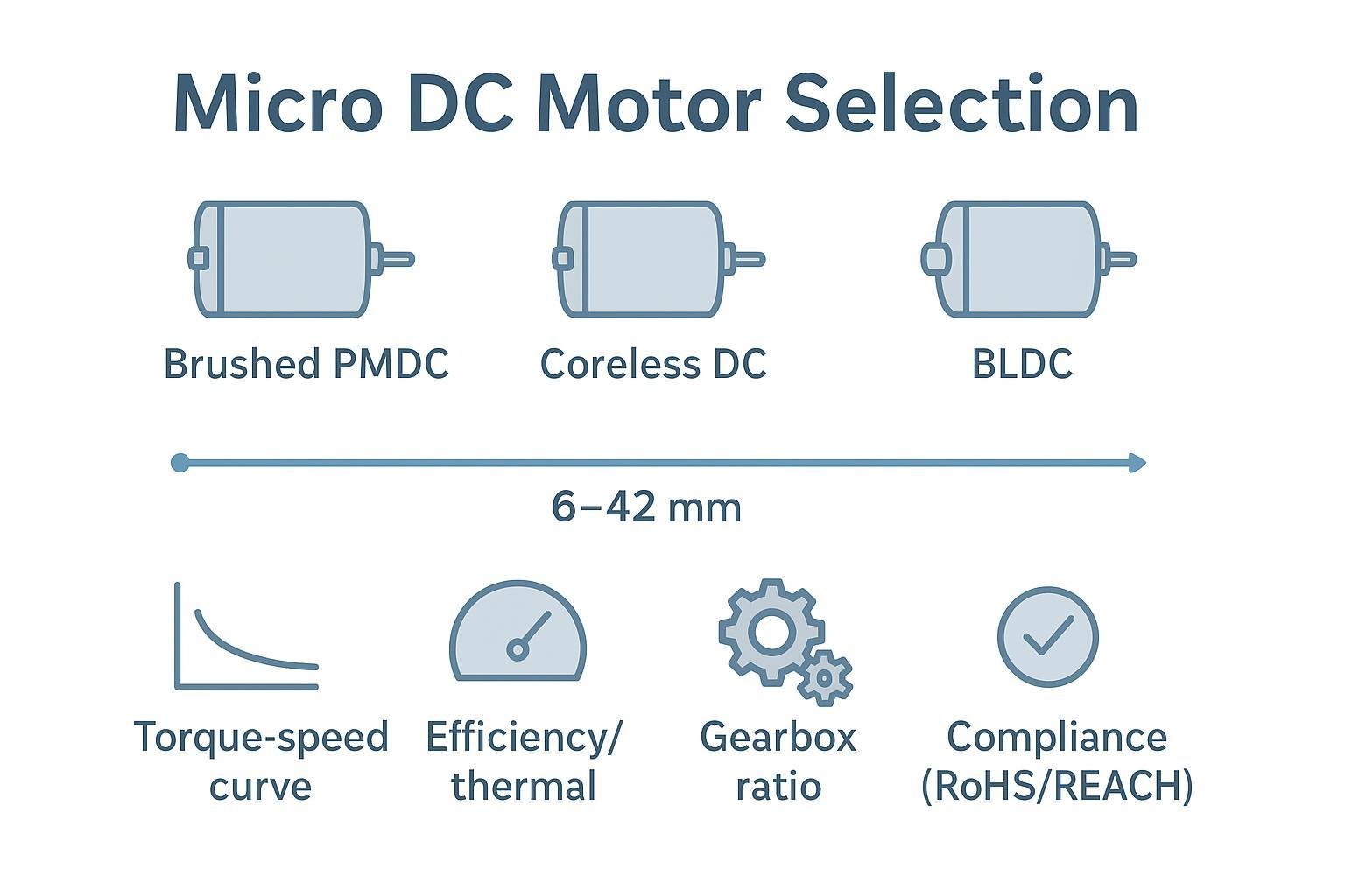
How brushed PMDC, coreless DC, and BLDC micro motors differ in the 6–42 mm class
A quantitative sizing workflow (torque, speed, peaks, margins, efficiency, and thermal limits)
Where gearboxes help—and where they create backlash, losses, and inertia problems
How to pick encoders and pair drivers (H-bridge vs. ESC/FOC)
What compliance and QA documentation to request before DVT
Scope and assumptions:
Form factor: 6–42 mm micro motors and gearmotors
Point of view: second person, engineering-first
Goal: choose an operating point you can test, validate, and source reliably
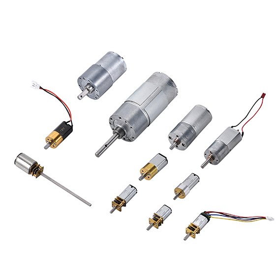
Motor types and sizes
In micro sizes, your motor type choice is usually a trade between control simplicity, efficiency, noise, lifetime, and cost—and the “best” answer changes with duty cycle.
Product taxonomy: brushed, coreless, and BLDC
For OEM teams, it helps to separate two ideas:
Motor principle: brushed DC, coreless DC (a brushed construction), or BLDC
Form factor “families” used in sourcing conversations: N20, N30, 030, etc.
This guide primarily classifies motors by principle, because it drives your controller, EMI, lifetime, and efficiency choices. Then, within brushed families, you’ll see N20/N30/030 as common packaging shorthand.
Brushed PMDC: traits and use cases
A brushed permanent-magnet DC (PMDC) motor is the simplest path to motion: apply DC or PWM through an H-bridge and you get controllable speed and bidirectional torque.
What it’s good at:
Low system complexity (no commutation electronics)
Low cost and broad supplier availability
Good short-term overload tolerance in many cored designs because the iron core can help conduct heat away from the windings
Where it bites you:
Brushes and commutation create wear and electrical noise (EMI risk), which you’ll need to filter and manage at the system level. For background on brush-motor EMI mechanisms and mitigation, Johanson Dielectrics summarizes practical filtering principles in “EMI DC Motor Filtering Basics”.
A deeper control-centric selection guide (H-bridge vs. brushless drivers) is covered by Texas Instruments in “Brushless-DC Motor Driver Considerations and Selection Guide”.
When you pick brushed PMDC in 6–42 mm, you’re usually choosing speed/torque per dollar and quick integration over maximum life.
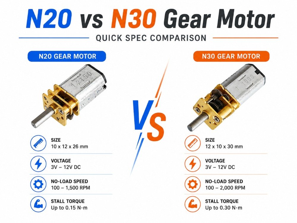
N20 vs N30 vs 030 quick comparison
These “names” are commonly used as sourcing shorthand for tiny DC motor form factors. Treat them as packaging cues, then confirm the exact drawing and performance curves.
Family | Typical envelope | Relative torque capability | Relative speed capability | Best-fit use cases | Notes |
|---|---|---|---|---|---|
N20 | ~12 mm class | Low–medium | Medium–high | Smart locks, small actuators, compact pumps/valves, tiny gearmotor modules | Very common in micro DC motor and micro gear motor assemblies |
N30 | ~15 mm class | Medium–high | Medium | Higher load actuators, latch/drive mechanisms, compact industrial modules | More copper volume vs N20; often chosen when you need margin |
030 | ~10–12 × 18–24 mm class | Low–medium | High | High-speed light-load mechanisms, wearables, small optics drives | Often paired with precious-metal brushes; validate life and thermal limits |
Keyword note: if you’re doing an N20 N30 motor comparison, the most reliable discriminator isn’t “RPM” in a catalog table—it’s whether the motor can hold your continuous operating point thermally once you add gearing and enclosure constraints.
Coreless DC: response, noise, limits
“Coreless DC” typically means a brushed motor whose rotor winding is self-supporting (no iron core). That has two big implications:
Very low rotor inertia → fast acceleration, responsive control loops
Reduced magnetic losses → often higher efficiency at the same operating point
A practical comparison of coreless vs. cored brushed behavior is discussed in Progressive Automations’ overview.
The engineering catch: coreless designs can be thermally unforgiving. With less iron mass, you can’t rely on the rotor to buffer heating during peaks. If your load has frequent stall events or long high-torque dwell, coreless can fail “quietly” (winding overheating) unless you instrument temperature and current early.
BLDC: efficiency, life, control
Brushless DC (BLDC) motors remove mechanical commutation and shift it into electronics. That usually improves:
Lifetime (no brushes to wear)
Efficiency (less friction and arcing losses)
Noise/EMI profile (no brush arcing), although switching edges in the drive can still create EMI if your layout/filtering isn’t disciplined
The selection trade is that BLDC requires a driver/ESC and control strategy. Monolithic Power’s primer “Brushless vs. Brushed DC Motors” is a useful high-level reference for how that system complexity relates to performance.
In the 6–42 mm envelope, you’ll often end up with BLDC when your spec is continuous-duty, efficiency-sensitive, or life-limited by brush wear.
A quick size and capability comparison for OEM scoping
Early in a program, you usually don’t need “perfect numbers.” You need a defensible envelope so you can shortlist options, prototype, and iterate.
Important: the ranges below are typical examples seen across common miniature DC motor windings and gearmotor stacks. Actual values depend on winding selection, duty cycle, thermal path, and gearbox design. Validate with your supplier’s curve and your own dyno/thermal tests.
Category | Typical outer size (envelope) | Typical rated voltage | Typical no-load speed | Typical rated torque | Typical gearbox ratio options | Typical notes |
|---|---|---|---|---|---|---|
Brushed miniature DC motor | ~10–24 mm OD/height class | 1.5–12 V | ~5k–20k RPM | ~3–40 mN·m | 10:1–1000:1 | Lowest drive complexity; brush wear + commutation EMI to manage |
Coreless brushed DC motor | ~6–22 mm OD class | 1.5–12 V | ~8k–30k RPM | ~1–25 mN·m | 5:1–500:1 | Very fast response (low inertia); watch thermal during peaks/stall events |
BLDC micro motor | ~12–42 mm OD class | 6–24 V (common), higher possible | ~3k–30k RPM (drive-limited) | application-dependent | 4:1–300:1 | Best for long life/continuous duty; requires ESC/FOC and clean layout |
Small gear motor / micro gear motor | motor + gearbox stack | 3–24 V typical | output speed set by ratio | output torque set by ratio + efficiency | 10:1–1000:1 | Great for torque and speed reduction; adds backlash, losses, and noise |
If you’re specifically scoping for small gear motor or micro gear motor options, start from your output torque/speed, then back-calculate the required motor operating point and ratio.
Quantitative sizing framework (micro DC motor selection guide)
If you want a motor spec that holds up, treat sizing as an operating-point problem:
define torque and speed requirements (including peaks),
pick an operating point on the torque–speed curve that’s efficient and thermally safe,
validate with measurements.
Key selection parameters for micro DC motor and gearmotor stacks
If you keep only four parameters in view, keep these:
Torque: define continuous and peak at the load. Use gearing to move the motor into a healthier speed band, but verify thermal rise at the motor.
Voltage: confirm your true supply range (battery droop, regulator limits) and choose a winding that hits your operating point without living at high current.
Speed: treat output RPM as a system result (motor curve × ratio × losses). Don’t “spec RPM” without tying it to torque.
Gear ratio: use ratio to trade speed for torque, but budget for efficiency loss and backlash.
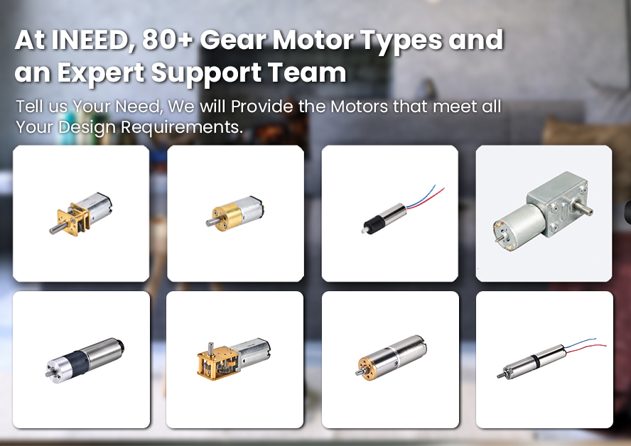
When you want to browse category options before narrowing to a specific winding/gear ratio, these internal pages are the best starting points:
For miniature brushed micro motors and related options, see INEED micro DC motor options.
For small gear motor options that emphasize compact spur gear trains, see INEED spur geared motors.
For longer-life, electronics-commutated solutions, see INEED brushless DC motors.
Define torque, speed, peaks, margins
Start with three numbers:
Required output speed at the load (RPM)
Continuous torque at the load (the torque you need for steady operation)
Peak torque (startup, transient loads, or short overloads)
Convert linear loads to torque early. If you’re driving a leadscrew, wheel, or pulley, compute torque at the shaft with your geometry and friction assumptions—not just “force needed.”
Then apply margins:
For continuous duty, a conservative rule of thumb is sizing so the motor’s continuous capability exceeds your required continuous torque with margin, and that your power requirement isn’t right at the motor’s maximum. The MIT Fab Lab note “How to Select a DC Micromotor” explicitly recommends selecting a motor rated roughly 1.5–2× the desired output power relative to its maximum output power.
For peak torque, don’t confuse “stall torque exists” with “stall torque is usable.” Bodine’s explanation of “peak or obtainable torque” is helpful: peak torque is limited by thermal and demagnetization constraints, and it’s inherently time-bounded.
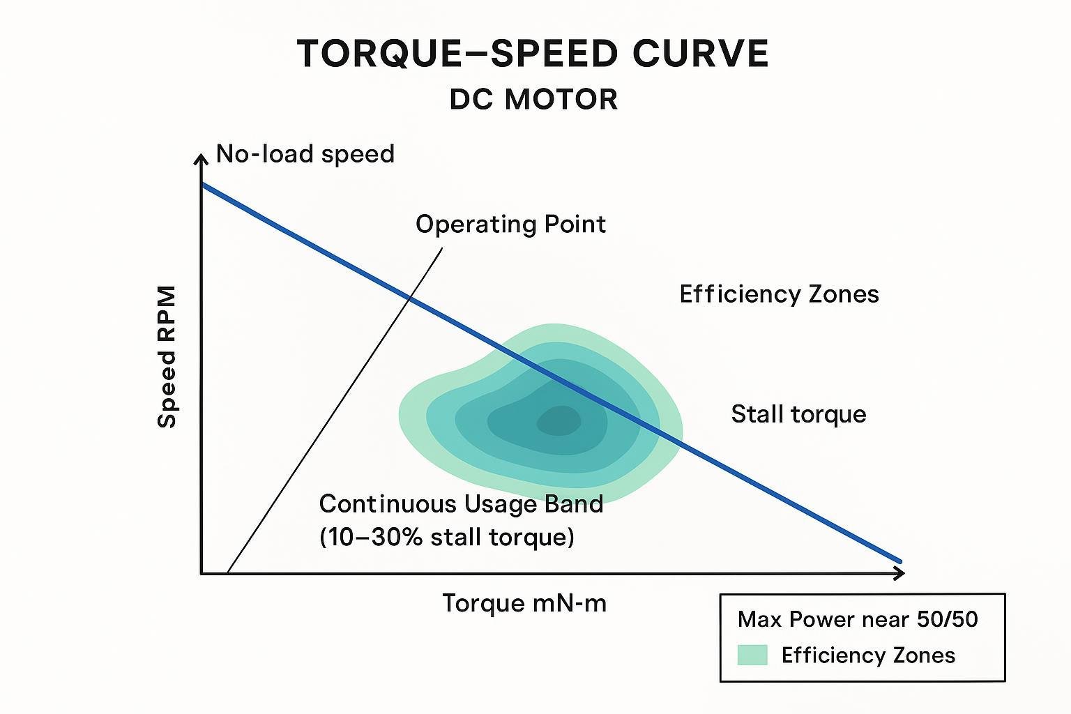
Torque–speed curves and efficiency
For brushed and BLDC motors (ignoring saturation and controller limits), the torque–speed line is close to linear: speed decreases as torque increases.
What matters for selection isn’t the line—it’s where you operate on it.
A practical way to interpret motor/gear-motor curves is ISL Products’ note on “How to read DC motor & gear motor performance curves”. They describe a “continuous usage range” that often sits at a fraction of stall torque, where efficiency and temperature rise are manageable.
Working heuristics you can use during early sizing:
Avoid designing the steady operating point near stall.
Expect efficiency to peak away from stall; treat max-power points as not continuous-duty points unless a datasheet explicitly supports it.
Thermal limits and derating
Thermal failure is the most common reason a “works on the bench” micro motor dies in DVT. That’s why you should treat thermal derating as a first-order sizing input, not a late validation detail.
Three things drive your temperature rise:
copper loss (
I²R) in the windingsiron loss (if present)
how well the motor case can dump heat into your product’s structure
Two practical derating realities:
Datasheet curves often assume a defined mounting or ambient condition; your enclosure, airflow, and conduction path can shift continuous torque significantly.
Peaks that look safe mechanically can still accumulate heat over a duty cycle.
⚠️ Warning: If your design ever sits near stall torque for more than brief transients, instrument current and winding temperature early. “It survived 10 seconds” is not a thermal qualification.
Gearboxes and inertia
A gearbox is how you reconcile two truths. Treat this as micro motor gearbox selection, not an afterthought, because it changes efficiency, noise, backlash, and control stability:
small motors are happy at higher speed and modest torque
your load often wants low speed and higher torque
But gearboxes add losses, backlash, noise, and reflected inertia. If you treat them as a simple torque multiplier, you’ll end up with unstable control or an overheated stage.
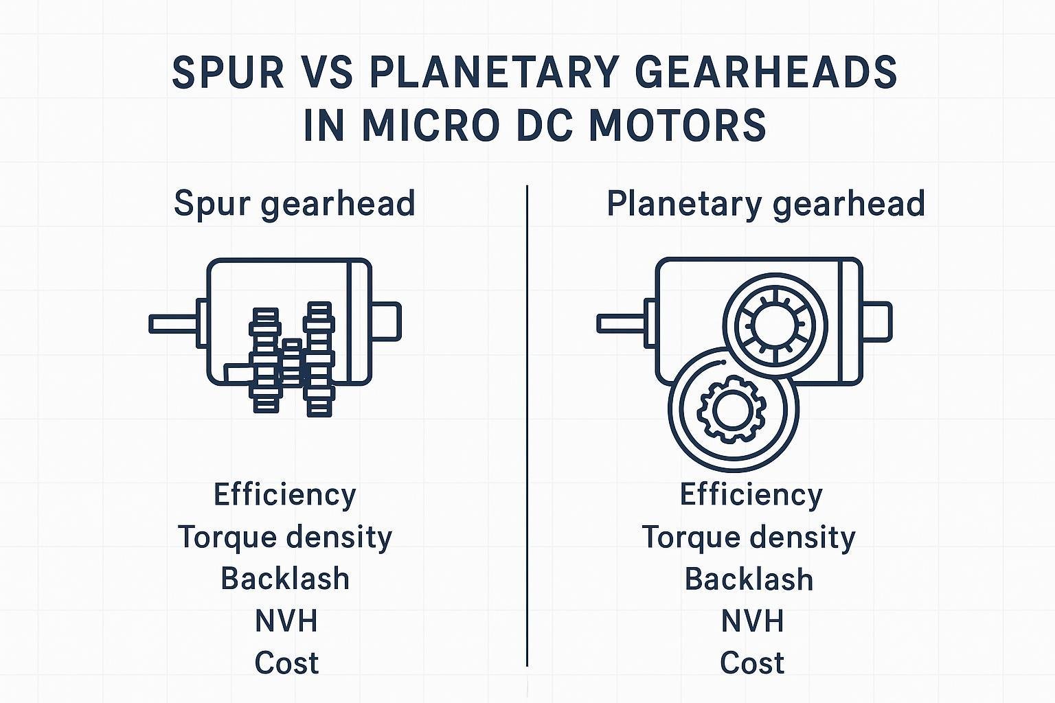
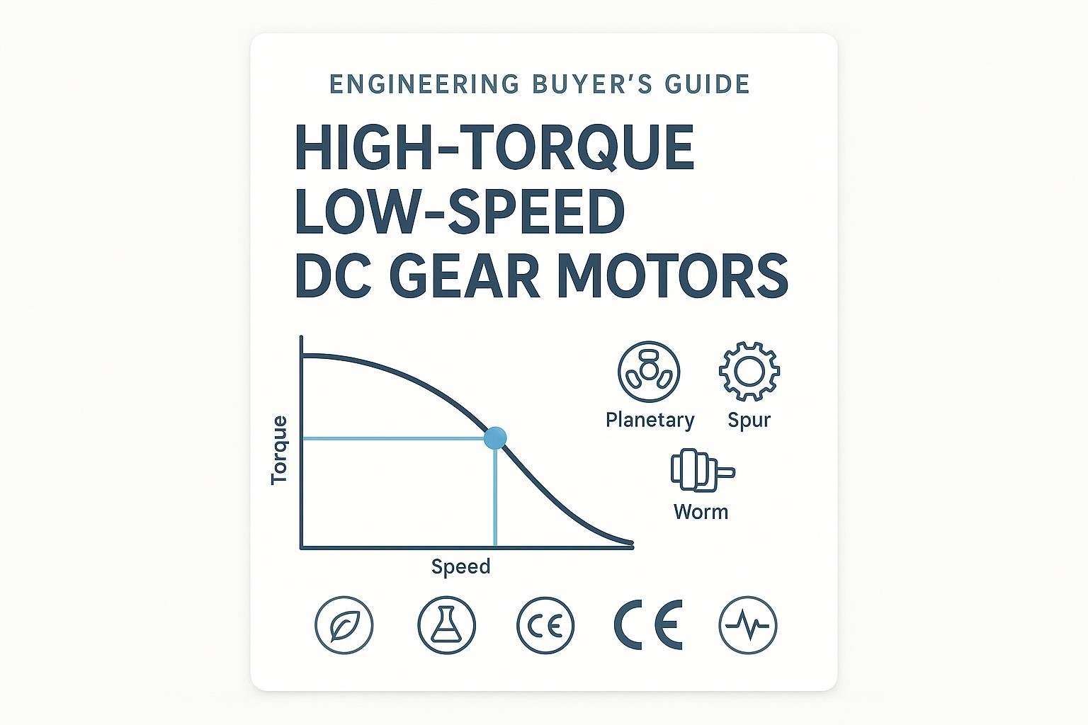
Planetary vs. spur vs. worm vs. harmonic
Practical selection framing:
Planetary gearboxes are commonly chosen when you need high torque density, coaxial packaging, and good efficiency.
Spur gearboxes can be cost-effective, but can be noisier and may require multiple stages for higher ratios.
Worm gearboxes can provide right-angle packaging and self-locking behavior, but typically trade efficiency for that benefit.
Harmonic drives are excellent for low-backlash precision, but are uncommon in true micro cost/size envelopes; when used, they’re usually tied to a very specific positioning requirement.
For backlash and gearhead fundamentals, FAULHABER’s technical PDF “Precision Gearheads Technical Information” explains why some backlash is functional (lubrication space, differential expansion) and how it’s measured.
Losses, backlash, lubrication, noise
Your effective output is the motor output times gearbox efficiency. If you’re stacking stages, losses compound.
Efficiency and noise aren’t independent:
High friction (especially in worm stages) turns into heat, and heat changes lubrication viscosity.
Gear mesh and tooth form drive acoustic signature; spur meshes tend to whine more at speed.
A practical servo-centric argument for why planetary designs often win on stiffness/backlash/efficiency is summarized in Linear Motion Tips’ explainer “Why are planetary gearboxes preferred for servo applications?”.
Inertia ratio targets and reflection
If you’re doing closed-loop motion control, inertia mismatch is where “good motor” becomes “bad actuator.”
Two rules to keep you honest:
Reflected load inertia to the motor side scales approximately with 1/ratio². That’s a benefit of gearing: it makes heavy loads look lighter to the motor.
But the gearbox adds its own inertia and compliance. If backlash/compliance is large, it can dominate control behavior even if the motor is well-sized.
If you need a working target, start by aiming for a reasonable load-to-motor inertia ratio after gearing (servo tuning becomes easier as mismatch decreases), then validate with step response and current peaks.
INEED Motors customization examples (ratios, shafts, encoders):
When you’re selecting a micro gearmotor in the 6–42 mm range, the configuration details often matter as much as the nominal ratio:
Gear ratios: You typically iterate ratios to land your operating point in a more efficient motor speed band, then confirm you still meet peak torque with margin. INEED Motors’ catalog focus on geared options (including planetary) is summarized on their planetary gear motors page.
Output shafts: For OEM integration, shaft geometry is where tolerances, bearing loads, and coupling constraints surface. It’s common to specify shaft length/diameter/flat/knurl/spline to match your coupling and assembly process.
Encoders on gearmotors: If your application needs repeatable positioning or speed regulation under load, you can integrate feedback at the motor or output stage. INEED Motors provides a starting point for options on their motor encoders page.
Keep these decisions tied to tests: backlash measurement at load, acoustic measurement at speed, and temperature rise at steady torque.
Typical application scenarios
Use these examples to sanity-check whether your motor principle matches the product risk profile (noise, life, control complexity, and thermal margin).
Medical devices
Prioritize predictable behavior under duty cycle, lower EMI risk, and documentation discipline.
Coreless can be a good fit for fast response with low vibration, but only if you control peak current and validate winding temperature.
BLDC tends to win for continuous-duty subsystems where brush wear would dominate life.
Drones and UAV payloads
Weight and efficiency dominate. For propulsion-like needs, BLDC is common; for tiny mechanisms (gimbals, latches, optical shutters), you’ll still see miniature brushed/coreless.
Gearboxes can help torque, but watch backlash and acoustic signature if you’re stabilizing optics.
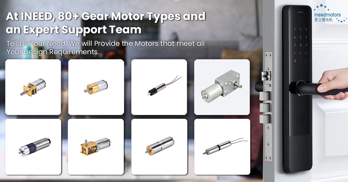
Smart home devices
Many products are cost- and integration-driven: brushed + gearbox remains common for locks, valves, and compact actuators.
If the product is quiet-room sensitive, validate gear noise and consider drive strategies (PWM frequency, FOC) that move tonal noise out of audible bands.
Wearables
Size and power are the constraints. You typically need tiny DC motor form factors with careful thermal management.
Choose coreless when responsiveness matters, but avoid long stall events and build a robust current limit.
Encoders and drivers
Micro motors are easy to spin. They’re harder to control precisely once you add gear backlash, variable load torque, and EMI.
CPR/PPR selection and speed limits
Resolution is a trade: more counts improve control granularity but increase edge rate and make noise problems more visible.
A few practical points:
In quadrature encoders, “CPR” is often 4× “PPR,” depending on how the vendor defines each term. US Digital explains resolution definitions in “Understanding encoder resolution and its 3 forms”.
Your electronics must handle encoder frequency:
f ≈ RPM × PPR / 60(then multiplied by decode mode).If you need homing after power cycle, you want an index (Z) channel or an external reference sensor.
For motor-family integration constraints and incremental encoder options, FAULHABER’s overview of incremental encoders is a useful reference point for what “real” encoder product families look like.
H-bridge vs. ESC/FOC pairing
Driver selection should follow motor type:
Brushed DC: H-bridge (full bridge) with PWM for speed and direction.
BLDC: a 3-phase inverter/ESC. Commutation can be six-step (trapezoidal) or sinusoidal/FOC.
If you’re building an OEM design, you’re usually choosing between implementation complexity and performance:
Six-step is simpler, but introduces more torque ripple.
FOC generally improves smoothness and can reduce acoustic noise, but increases firmware/control-loop complexity.
TI’s application note provides a clear engineering framing for BLDC driver selection trade-offs.
Signal integrity and index channel
Signal integrity becomes a mechanical/electrical co-design problem at small scales:
Keep encoder cabling short where possible.
Use shielding and differential signaling when the environment is noisy.
Treat the index channel as a “system feature,” not an encoder checkbox: if your assembly tolerances, gear backlash, or slip mechanisms can shift the output, decide whether you need homing at the motor or at the load.
Pro Tip: If you’re struggling with closed-loop stability, validate the encoder edge quality and noise margin on a scope before you touch PID gains.
Compliance and QA
In high-tech OEM programs, motor selection isn’t only about performance—it’s about whether the supplier can support documentation, change control, and traceability through MP.
RoHS/REACH documentation
If you sell into the EU, RoHS and REACH evidence should be part of your supplier qualification package, not a last-minute checkbox.
For baseline scope and intent, the European Commission’s official page on the RoHS Directive is the right reference.
Practically, request:
Declarations of Conformity (RoHS/REACH)
material/substance reporting and exemption statements where relevant
update cadence for SVHC list changes
ISO 13485 and test reports
If the motor is used in a medical device (or in a subsystem that falls under your device’s quality controls), ISO 13485 matters—especially for supplier qualification and documentation discipline.
ISO’s overview of ISO 13485 (Medical devices — Quality management systems) is a good anchor for what the standard is trying to enforce.
Even outside medical, request test artifacts that map to your risks:
torque–speed curves with test conditions
thermal rise at defined load and ambient
noise/vibration measurements if acoustics matter
life testing notes (what was run, duty cycle, environment)
IP ratings and traceability
If your motor lives in dust, fluids, or aggressive cleaning environments, ask for IP test basis and boundaries:
what assembly the IP rating applies to (motor only vs motor+connector vs motor+gearbox)
whether the rating is tested or inferred
For traceability, insist on batch/lot coding and change-notification expectations. Without traceability, field returns become “guesswork at scale.”
FAQ
What’s the difference between a micro DC motor and a small gear motor?
A micro DC motor is the motor itself (brushed, coreless brushed, or BLDC). A small gear motor (also called a micro gear motor) is that motor paired with a gearbox to reduce speed and increase output torque. The gearbox changes more than torque—it also adds losses, backlash, and reflected inertia, so you should validate efficiency, noise, and temperature rise at your real duty cycle.
For N20, N30, and 030 families, which one should I pick first?
Use them as packaging shortcuts, then decide based on your load:
Start with N20 when space is tight and your load torque is modest.
Move to N30 when you need more continuous torque margin or better thermal headroom.
Consider 030 when you need higher speed in a compact envelope and your load is light.
Whichever you choose, confirm that the motor can hold your continuous operating point (not stall torque) once you add gearing and enclosure thermal constraints.
When should I choose BLDC over brushed or coreless brushed?
Choose BLDC when your program is limited by lifetime (brush wear), continuous-duty efficiency, or maintenance risk. Brushed and coreless brushed designs can still be the fastest path to integration for intermittent-duty products, but you’ll want to manage commutation EMI and peak current carefully—especially if your mechanism can stall or dwell at high torque.
Conclusion
A micro DC motor selection guide is only useful if it helps you make a choice you can validate.
Key takeaways for 6–42 mm OEM designs:
Pick motor type based on duty cycle and risk: brushed for simplicity and cost, coreless for response (but watch thermal), BLDC for continuous-duty efficiency and life.
Size around an operating point on the torque–speed curve that’s efficient and thermally safe; treat stall as a limit, not a design point.
Use gearing to move the operating point, but pay for it in losses, backlash, and noise unless you specify and test those explicitly.
Close the loop only when your encoder resolution and signal integrity support it—otherwise you’ll be tuning around bad data.
Treat compliance (RoHS/REACH), documentation, and traceability as part of motor selection, not procurement cleanup.
Pre-DVT validation checklist:
Confirm continuous and peak torque requirements with measured load data
Verify operating point on the motor curve (and re-check after gearing)
Measure current and temperature rise at worst-case ambient
Measure noise/vibration if it’s a product requirement
Validate control stability with real harness lengths and EMI environment
Collect RoHS/REACH docs; confirm change-notification and traceability expectations
Next steps:
Build a small prototype set (motor + gearbox + encoder + driver) and run a dyno characterization (torque–speed, efficiency, temperature rise) under your real duty cycle.
If your product is EMC-sensitive, do an early bench pre-scan so commutation and switching noise don’t ambush DVT.
If you want supplier support while you iterate ratios/shafts/feedback options, start with an application review and a short list of configurations. For geared options, INEED Motors’ geared motor selection guide is a practical starting point.