Spur Gear Motors (DC Micro Gearmotors)

INEED Motors designs and manufactures compact DC spur gear motors for cost‑efficient speed reduction and reliable torque output. Choose from multiple gear ratios, motor types (brushed/coreless/BLDC), and options like encoders and custom shafts.

From prototypes to mass production, we support OEM/ODM projects with fast engineering response, stable quality control, and complete technical documents (datasheets, curves, 2D/3D CAD).
Tell us your target voltage, speed, torque, and installation limits—our team will recommend the best spur gearmotor configuration within 24 hours.

  • Diameter: 12–37 mm
  • Voltage: 1–24 VDC
  • Speed: 0.5–5000 rpm
  • Load torque: 0.1 g·cm – 200 kg·cm
Custom Spur Gear Motors | INEED Motors
See All of Our Spur Gear Motors

Filter by diameter, voltage, speed, and torque. If you don’t see an exact match, we can customize gear ratio, shaft, connectors, and encoders based on your drawings.

How to Select a Spur Gear Motor (Fast Guide)

Step 1 — Define your requirements
• Target output speed (rpm)
• Required torque (continuous & peak)
• Duty cycle and lifetime target

Step 2 — Choose gearbox & gear type
Spur gear motors are efficient and cost‑effective for lower‑to‑moderate torque applications. For lower noise, consider helical gears (if available).

Step 3 — Pick motor technology
• Brushed DC: simple control, cost‑effective
• Coreless: smoother operation, lower inertia, high efficiency
• BLDC: long life, high power density

Step 4 — Select options
• Encoder (speed/position feedback)
• Shaft type (D‑cut / round / threaded / custom length)
• Connector/wiring (lead wires, pin type, Molex/Hirose etc.)

Send your speed/torque target — we will recommend 3 candidate configurations within 8 hours.

Spur Gear Motor vs Planetary Gear Motor

Spur gear motors are a cost‑effective solution with high transmission efficiency and a simple structure. Planetary gear motors distribute load through multiple contact points, which often provides higher torque density and load capacity in compact designs.

When spur is a better fit: cost‑sensitive projects, moderate torque needs, simple integration.

Spur Gear Motor vs Worm Gear Motor

Spur gear motors are typically more efficient and suitable for higher speed operation. Worm gear motors can offer large reduction ratios in compact right‑angle layouts and may provide self‑locking behavior in some designs, but usually at lower efficiency due to sliding friction.

Typical Configurations (Customizable)

ItemOptions
Diameter12 / 16 / 20 / 24 / 37 mm
Voltage3 / 6 / 12 / 24 VDC (custom)
Gear typestraight‑cut / helical
Encoderoptional (magnetic / optical)
ShaftD‑shaft / round / threaded / custom
Documentsdatasheet, torque curve, 2D/3D CAD

What is Spur Gear?

Small Gear Motor

Spur gear:

Spur gears

Straight gears or spur gears are cylindrical gears with teeth that run parallel to the rotational axis. The teeth extend radially from the gear, allowing for efficient power transmission.

Spur gears do not generate axial thrust by their tooth loads. They excel at moderate speeds, offering reliable and efficient power transmission. However, it’s important to note that at high speeds, spur gears tend to produce more noise compared to other gear types.

Customization of Spur Gear Motors

Precision gear motor are designed to simplify construction, reduce costs, and provide reliable and efficient low-torque performance. To learn more about how DC spur gear motor customization can benefit you, kindly see our Spur Gear Motor Customization Guide below:

Open-Frame spur gearhead

Open Frame

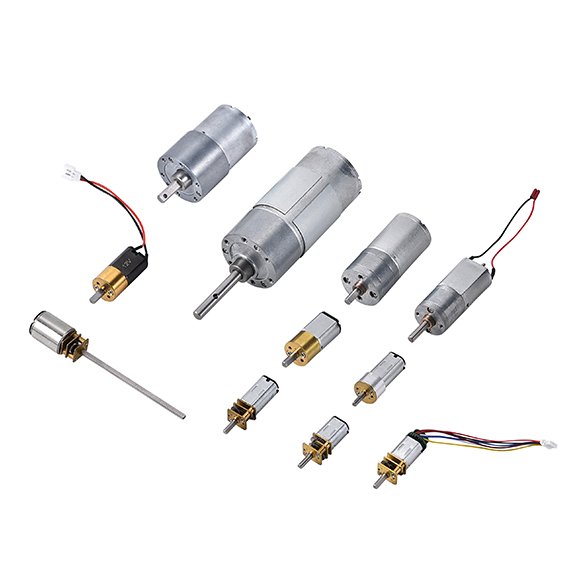
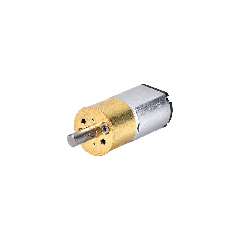
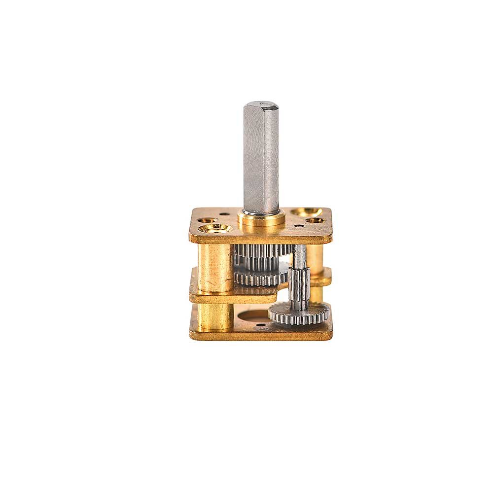
Most of our designs use an open construction with square or rectangular gearboxes.

Closed-Frame spur gearhead

Closed Frame

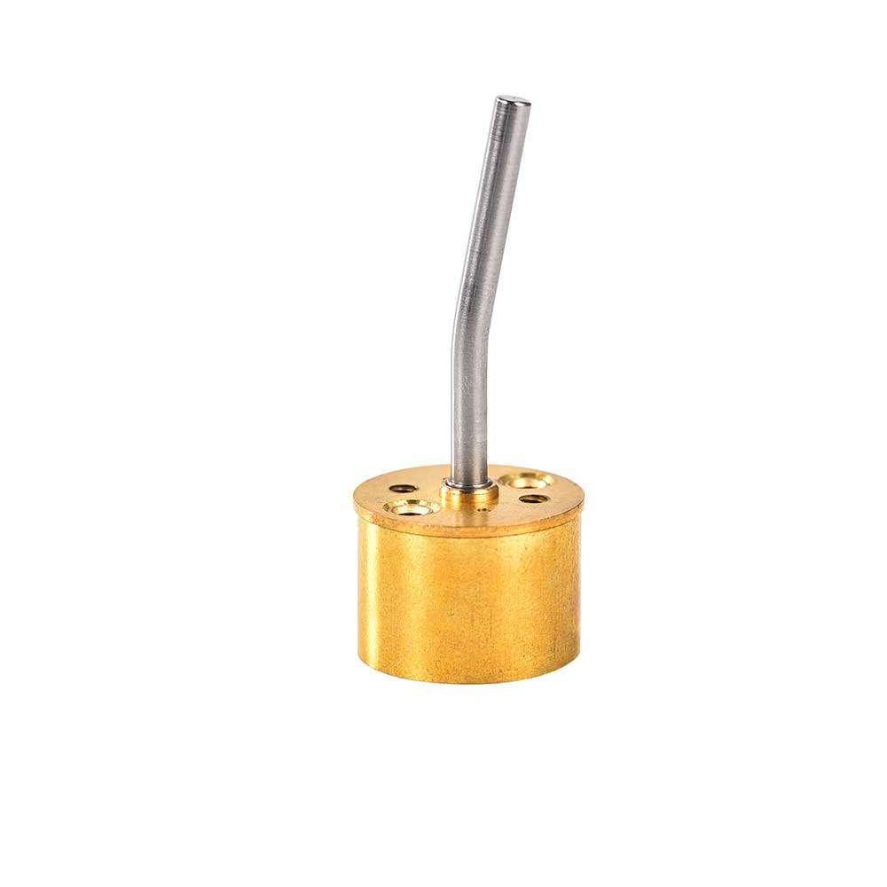
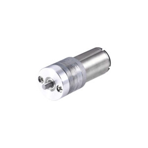
The closed gearbox is designed to be circular to make it more practical and can cover the gear and keep debris out.

Shaft-Solution

Shaft Solution

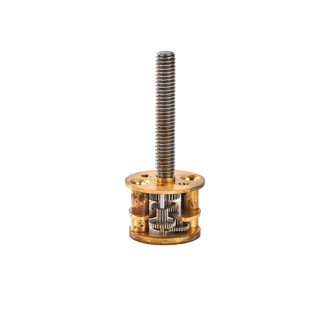
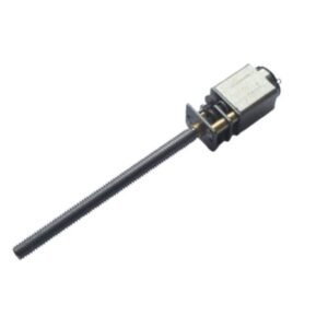
We offer customization of shafts in various lengths, round types, location holes, D-cut, screw shafts, and more. Additionally, we can add gear to an output shaft if desired, all to meet customer drawings.

Spur-Offset and foldback spur gearhead

Offset and foldback

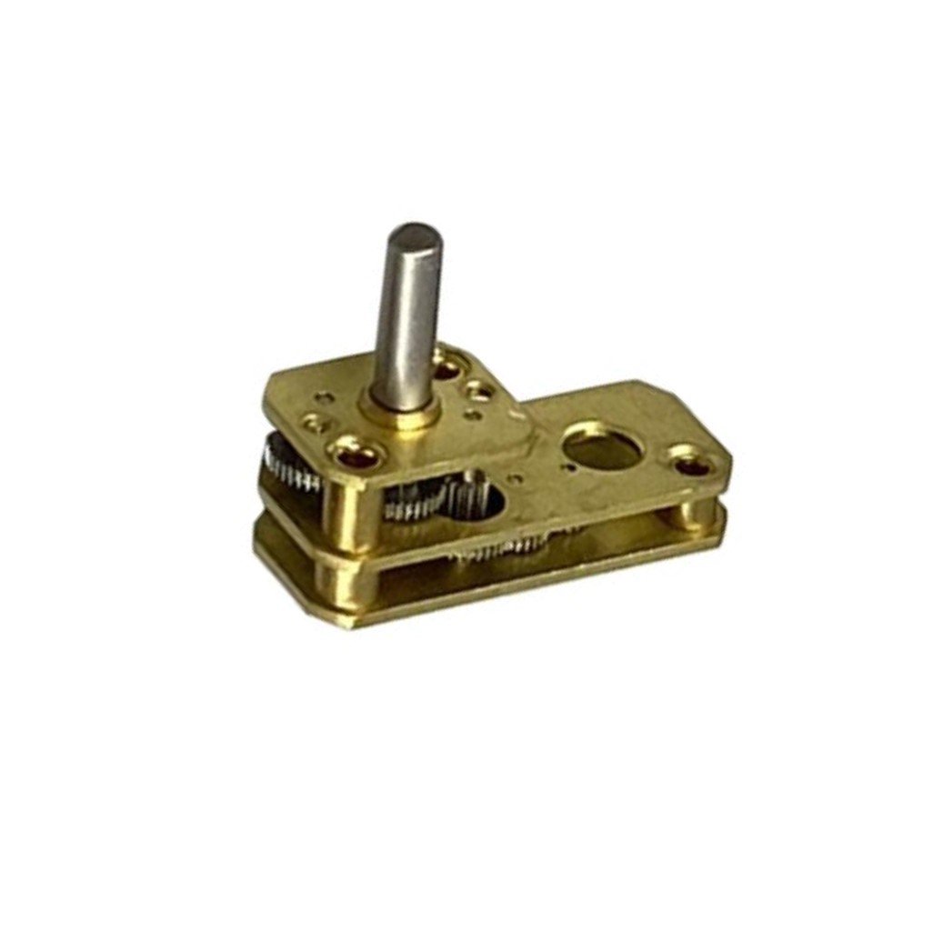
If space is limited, you can choose between a fold-back gearbox or a non-concentric offset gearbox shaft for your design.

N20 gear motor Encoder

Matching Encoder

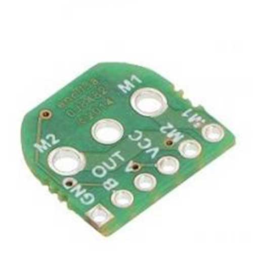
Different encoders can combine with INEED DC gear motors. The encoders are ideal for commutation, position control, speed, or count. That means each shaft position within a revolution is assigned a unique angular value through the encoder. Click Pic to find more about our encoders.

Adding connectors

Adding connectors

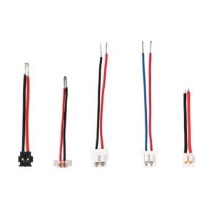
A spur gear motor can be connected to other components using a variety of different methods including pin type, lead wires, and connectors. Connectors that can be used to attach the motor to Molex, ACES, ELCO, and Hirose components are all available. Click Pic to find more connectors.

The Structure of Spur Gear Motor

One notable distinction of spur gear motors compared to planetary gear motors is that the output shaft is typically eccentric. However, for some products, according to the installation requirements, the output shaft can be made into a shaft in the center by the gear motor manufacturer’s internal machining.

The structure of a spur gear motor is simple, making it more affordable compared to planetary gear motors. The spur gearhead is added to the motor to reduce the output speed and increase the torque. We use high-quality steel or brass gears to ensure maximum strength and longevity. These gears can be coupled with iron core, coreless, and brushless motors.

A spur gear motor is a type of cylindrical gear motor that consists of several spur gears arranged in parallel axes.

Since the teeth of the gears are parallel to the axis of installation, no axial thrust is generated. The profile of the spur gears follows an involute curve, and only one pair of teeth engage at a time, resulting in purely radial forces on the shaft. In other words, all loads are borne entirely by the single contact point between the two gears. Additionally, the meshing action of spur gears can generate higher forces on the teeth, resulting in slightly louder noise compared to planetary gear motors. Spur gear systems have no sliding losses, making them generally more efficient in power transmission. By adding more gear stages, the reduction ratio can be increased, thereby lowering the output speed and increasing the torque. 

The difference between a spur gear motor and a planetary gear motor? 

The Structure of Spur Gear Motor

Engineering Support & Customization

INEED Motors has over 10 years of experienced R&D engineers and several advanced R&D laboratories.

motor-design
Customized-motor-equipment

• 10+ years motor & gearbox R&D


• 80%+ projects are customized


• Deliverables: datasheet, motor curves, 2D/3D drawings, DFM suggestions

Gear-Mesh-Tester
Gear-Measurement

Quality Control and Reliability

INEED Motors is equipped with various precision machining and quality testing equipment. We have established a comprehensive inspection process, covering material selection, production process monitoring, product testing, and other aspects. We have also established a perfect after-sales service system to respond to customer inquiries and needs promptly, rather than go away after delivery.

Inspection-motors
Finished-product-testing
Gear-Measuring-Center

The Advantages of Spur Gear Motor

Simple

Its simple and compact design makes them easy to design and install, even in limited or restricted spaces.

Constant Speed Drive

These gears increase or decrease the speed of the shaft with a constant speed and high precision

Reliability

The spur gears are unlikely to slip during operation, and their durability reduces the risk of premature failure.

Cost-Effective

Its simplicity of design allows for greater manufacturability, making their manufacturing and purchasing costs lower.

Efficiency

Spur gear systems have power transmission efficiencies between 95% to 99%, enabling large amounts of power to be transmitted between multiple gears with minimal power loss.

Contact Us

You need our support, and we are ready to provide assistance.

Struggling with DC motor complexities? We specialize in custom small gear motor and micro DC motor, offering expert solutions to simplify design, manufacturing, and delivery. Let’s work together to make it easier for you. 

Contact us today!  

You can easily upload your 2D/3D CAD design files, and our sales engineering team will provide you with a quote within 8 hours.

FAQ for Spur Gear Motor

Spur gear motors are a combination of spur gearboxes and motors, with the output shaft often being eccentric and using a voltage of 3-24V. They are the most easily visualized precision cylindrical gear motors, transmitting motion between two parallel and coplanar shafts with straight and parallel teeth.

Spur motors find applications in diverse industries such as robotics, automation, medical devices, automotive, and consumer electronics. They are suitable for tasks requiring precise and reliable torque control.

Yes—most spur gear motors are backdrivable, meaning the output shaft can be driven by an external load when power is off. Backdrivability depends on the gear ratio, friction, lubrication, and load. Higher ratios generally reduce backdrivability, but spur gearboxes typically do not provide a true self‑locking function like some worm gear designs.
If your application needs holding position when unpowered, consider adding a brake, using a worm gear solution, or designing a mechanical locking/holding mechanism.

A practical way is to start from the load torque and add a safety margin:

  1. Determine the load type (constant load, intermittent peaks, acceleration/deceleration).
  2. Estimate required torque at the output shaft:
    • For rotating loads: include friction + any external resistance, and add acceleration torque if speed changes quickly.
    • For linear motion (lead screw, belt, etc.): convert force to torque based on your mechanism geometry.
  3. Add a safety factor (commonly 1.3× to 2× depending on duty cycle and shock loads).
  4. Check both continuous torque and peak/stall torque to avoid overheating or gear wear.

If you send us your target speed (rpm), load condition, and space limits, we can recommend a motor/gear ratio combination and provide torque curve references.

According to different given conditions, there are two ways to calculate the speed reduction ratio of a spur gear motor:

1. Given the output speed and the rated speed of the motor (input speed): Spur gear ratio= Output speed/Input speed.

2. Given the number of teeth of the driving gear and the driven gear: Spur gear ratio= The number of teeth of the driving gear/The number of teeth of the driven gear.

Spur gear motors, aka electric gear motors, are designed for low-maintenance operation. Routine inspections for lubrication, wear, and alignment may be recommended to ensure optimal performance and longevity.

Spur gears have straight teeth parallel to the shaft. They are simple, efficient, and cost‑effective, but can be noisier at higher speeds because the tooth engagement is more abrupt.
Helical gears have angled teeth, which provides smoother and more gradual meshing. This typically reduces noise and vibration and can improve running smoothness, but it may add cost and can generate axial thrust that requires proper bearing support.
If your application is sensitive to noise or requires smoother motion, helical gears are often a better option; for cost‑driven designs with moderate speed, spur gears are usually preferred.

Noise is mainly affected by:

  • Gear tooth quality and machining precision
  • Operating speed (higher rpm often increases noise)
  • Gear material and lubrication
  • Load level and alignment in your assembly
  • Housing design (open vs closed gearbox) and vibration isolation

Backlash (free play between meshing gears) is influenced by:

  • Gear train design and tolerances
  • Number of gear stages and gear ratio
  • Wear over time and lubrication condition
  • Bearing support and shaft alignment

For low‑noise or low‑backlash requirements, we can evaluate options such as improved gear precision, optimized lubrication, helical gearing (when applicable), and encoder feedback for control compensation.

Motors Catalog Download

Download and view the full series catalog for free

Contact Us

You need our support, and we are ready to provide assistance.

Motor products pose complexities in understanding, specifying, and integrating, with no industry standards. We offer expertise to mitigate design, manufacturing, and supply risks.

Contact our team now.

You can easily upload your 2D/3D CAD design files, and our sales engineering team will provide you with a quote within 24 hours.

Contact Us

You need our support, and we are ready to provide assistance.

You can easily upload your 2D/3D CAD design files, and our sales engineering team will provide you with a quote within 24 hours.