Introduction
Most OEM engineering teams don’t face the brushed-versus-brushless question as a technology debate. They face it as a specification conflict. The product needs a set torque and speed at the output shaft, inside a fixed space, on a fixed supply, at a cost the business case can carry — and both motor families can often hit those numbers on paper.
The real decision comes down to the hard edges: the stall event during a jam, the noise target in a patient room, the EMC test that must pass before the product can carry a CE mark, the maintenance interval the end user will actually keep.
An application decision tree settles that conflict in a fixed order. It separates requirements that rule an architecture out from requirements that only make one option more attractive. That way, a team doesn’t trade away a safety or thermal constraint to win points on cost. Gates come first and are absolute. Scoring comes second and handles the real trade-offs that remain. Used this way, the tree gives you a selection record you can defend, not just a preference.
Work through the guide in three passes. First, run the gates in the Application Decision Tree section against your own requirement document and note which architecture survives. Second, if both survive, score them with the weighted framework using measured or supplier-verified data — not datasheet headline values. Third, prove the result on hardware: prototype the worst-case operating point, run it with the drive you plan to ship, and revisit your lifecycle and supply assumptions once you have real test data. Treat every number here as a starting range for sizing and questioning, not a substitute for your own verification.
Baseline: How the Two Architectures Differ
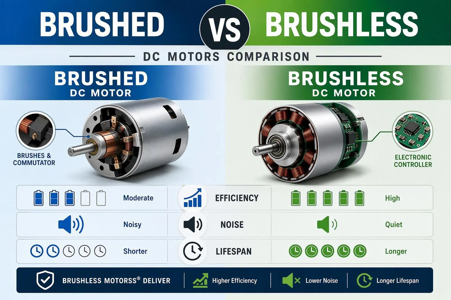
Both families make torque the same way. A rotor field and a stator field push against each other, and the current in the windings has to be switched as the rotor turns so the push stays in one direction. That switching is called commutation. The only real architectural difference is who does it: a mechanical contact set on the rotor, or electronics in a drive. Everything downstream — efficiency, service life, EMC — follows from that one split.
Brushed fundamentals
In a brushed DC motor, the permanent magnets sit in the housing as the stator, and the wound armature spins. Current reaches the windings through carbon or precious-metal brushes riding on a segmented commutator fixed to the rotor. As the rotor turns, each brush pair meets the next segment and reverses the winding current at the right moment. The setup is simple, needs no external electronics, and gives high starting torque, with speed set by varying the supply voltage. That’s why micro DC motors with brushed commutation remain common in cost-sensitive and high-inrush duties. The price is mechanical: brush and commutator wear, friction losses, arcing, and a heat path that runs from the windings through the rotor to the housing.
Brushless fundamentals
A brushless DC (BLDC) motor flips the layout: the windings are fixed on the stator and the permanent magnets rotate. Because the windings no longer move, they can be wired directly, so commutation moves into an electronic drive that energizes the phases in sequence. The drive needs to know where the rotor is — from Hall sensors or a sensorless estimation scheme — and usually uses PWM to control speed. That controller is the entry ticket: a brushless DC motor won’t run from a bare DC supply. In return, there’s no brush contact to wear, arc or shed particles, and the windings sit on the outer member where heat can escape more easily.
Key trade-offs and ranges
The practical differences fall into a handful of dimensions. The rest of this guide tests each one against your requirements.
Dimension | Brushed DC | Brushless DC (BLDC) |
|---|---|---|
Commutation | Mechanical, brush/commutator | Electronic, via drive |
Typical continuous speed band | roughly 1,000–10,000 rpm | Higher speeds achievable; low speed needs gearing or torque-motor design |
Speed regulation (good example) | about 10% | about 5%; 1–2% with a high-performance drive |
Brush/service life | commonly 2,000–5,000 h (carbon); ~1,000 h for precious-metal brushes | often 10,000 h+; can exceed 20,000 h, bearing-limited |
Thermal path from windings | Poor (rotor-mounted) | Better (stator-mounted) |
Drive electronics | Not required | Required |
Relative upfront cost | Lower | Higher |
These bands come from published motor-maker comparisons and are indicative, not guarantees. Allied Motion reports brush life of 2,000–4,000 hours for carbon brushes and about 1,000 hours for precious-metal types, with BLDC service life easily topping 20,000 hours. Haydon Kerk Pittman cites 2,000–5,000 runtime hours for brushes and 10,000+ hours for brushless units, which are then limited by bearings and environment. Brush life depends heavily on load, duty and brush material, so treat any figure as a test hypothesis for your application.
Compare: Brushed vs Brushless DC Motors
The comparison below follows the three areas where the architectural split shows up in a specification review: energy and speed capability, disturbance and heat, and longevity. Read each against your own duty profile. A difference that decides a continuous-duty application may not matter in an intermittent one.
Efficiency, power density, speed
Brushless designs usually win on efficiency. They remove the brush-commutator friction and voltage drop, and the drive can commutate the stator windings with very little loss. Dunkermotoren links brushed motors’ lower efficiency to exactly those friction and electrical losses, and points to the higher energy use and heat that come with them. The gap matters most where energy is scarce or duty is high. Battery-powered devices get more runtime, and continuously running industrial equipment adds up savings over time.
Power density follows the same logic. Brushed motors carry brushes and a commutator, which adds weight and caps output in a compact package, so their power-to-weight ratio is generally lower. Brushless motors deliver more power per unit of weight. On speed, brushed motors work best continuously between roughly 1,000 and 10,000 rpm, while BLDC designs can run faster and keep flatter speed-torque curves. Speed regulation is a related point: Allied Motion puts a good brushed motor at about 10% and a good brushless motor near 5%, tightening to 1–2% with a well-implemented high-performance drive.
Noise, EMI/EMC, and thermal
Brushed motors create electrical noise at the commutation point. Mabuchi Motor explains that the commutator switches winding current direction, and that occasional sparking between brushes and commutator at commutation is one cause of electrical noise. That noise travels two ways: as conducted line noise along the cables and as radiated noise into the air. In practice, it can make brushed motors harder to get through EMC testing. Brushless motors have no brush arcing and run more smoothly, so they generally produce less EMI and suit applications with strict electromagnetic compatibility requirements.
Heat is a structural advantage. In a brushed motor the windings sit on the inner rotating part, so heat has to cross an inefficient path to reach the housing. In a BLDC motor the windings are on the outer member, with a more direct route out. Haydon Kerk Pittman calls this lower thermal impedance for the brushless unit, which is why a brushless motor of the same size can deliver more continuous torque. The catch is integrated electronics: motor heat can affect onboard control electronics and force derating compared with a separate motor and drive.
Service life and maintenance
The brush-commutator interface is the main life limiter in a brushed motor. Allied Motion notes that replacing brushes isn’t just a brush swap. The commutator surface also wears and may need resurfacing, and a poor replacement job can ruin a motor — which is why some manufacturers use inaccessible brush designs to avoid warranty claims. Check the documentation and warranty before you open a housing for service. Brush material shifts the trade-off too: carbon brushes are robust and economical but shed wear particles that contaminate sensitive applications, while precious-metal brushes cut arcing, EMI and particles but are more fragile, shorter-lived and more expensive.
Brushless motors remove that wear mechanism entirely. The only wearing parts are the shaft bearings, so service life depends on bearing life and environmental conditions rather than on commutation hardware. Maintenance work shifts from planned brush replacement to drive reliability and, where present, sensor and cable integrity. For hard-to-reach or safety-critical installations, that shift alone can settle the architecture.
Application Decision Tree
Run the gates in the order given, and stop at the first one that rules an architecture out. A gate is a pass/fail test against a requirement you can document, not a preference. If you can’t evaluate a gate yet, that’s a data gap to close before scoring — not a reason to skip ahead.
Must-pass safety and thermal gates
Gate 1 — Ambient and winding temperature. Work out the expected operating temperature as temperature rise plus ambient, then compare it with the insulation class limit. IEC 60085 ties a 20,000-hour life expectancy to an insulation system run continuously at its class temperature: 130 °C for class B, 155 °C for class F and 180 °C for class H. Leroy-Somer’s explanation of IEC 60034-1 shows how to get the thermal margin by subtracting the temperature rise class and ambient from the insulation class temperature. A brushed motor’s weaker heat path burns through that margin faster. If the calculated margin is thin or negative, the brushed option fails and the decision ends here.
Gate 2 — Contamination and cleanroom limits. If the application can’t tolerate carbon particles, a carbon-brush motor is out, whatever the cost. Precious-metal brushes produce fewer particles but still wear. A brushless design removes the source.
Gate 3 — Stall and jam behaviour. Define your worst-case stall event and the winding temperature and drive current that come with it. Any motor that can’t survive a credible jam without going over its thermal limit fails, brushed or brushless.
Gate 4 — Regulatory scope. Confirm which directives and standards apply to the finished product before you select anything. In the EU, the RoHS Directive restricts ten substances in electrical and electronic equipment, and the EMC Directive requires apparatus to comply when placed on the market or put into service. Medical equipment brings its own collateral standard, IEC 60601-1-2, which sets electromagnetic disturbance requirements and tests.
Duty cycle, power source, noise gates
Gate 5 — Duty cycle and required life. Multiply your required operating hours by the duty cycle to get lifetime hours at the shaft, then compare that with each architecture’s credible life. A continuous-duty application needing 15,000 hours will wear out a 2,000–5,000-hour brush set several times over. An intermittent device that runs a few minutes a day may never reach brush wear-out inside its service life.
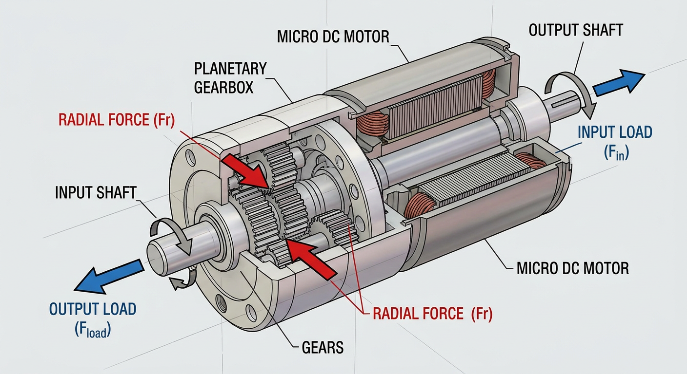
Gate 6 — Power source and available electronics. A brushed motor runs from a fixed DC supply and can be speed-controlled by varying voltage, which suits simple architectures. A BLDC motor needs a commutation controller plus power and cabling between motor and drive — cost and failure points that have to fit the enclosure and the budget. If there’s no room, power or skill for a drive, the brushless option fails this gate unless an integrated motor-and-controller unit works for you.
Gate 7 — Acoustic and electrical noise targets. If the product has a tight acoustic spec or must sit near sensitive electronics, weigh the sparking and radiated noise of a brushed design against the smoother running of a brushless one. Where a formal EMC limit applies, plan the pre-compliance test early instead of finding out the margin at certification.
Control and serviceability gates
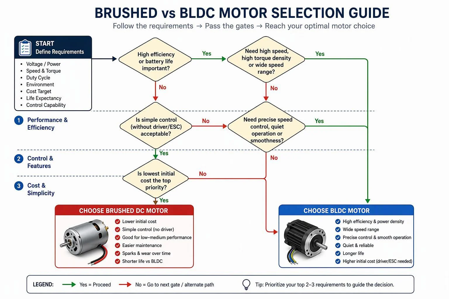
Gate 8 — Control precision. If you need precise speed and torque control across the speed range, brushless motors are usually the better fit — they hold steady torque across that range. If simple voltage-varied speed is enough, a brushed motor does the job without extra complexity.
Gate 9 — Service access. Decide whether the end user or a technician can reach the motor. Where access is impossible or the product is sealed for life, a wear item that needs periodic replacement is a liability. Where brushes are reachable and replacement is a planned, documented procedure, the brushed option stays viable.
Gate 10 — Integration and IIoT. If the product needs remote monitoring, predictive maintenance or a link to a plant network, the controller a BLDC motor already requires turns from a cost into an asset, because it can collect data and make precise adjustments.
If both architectures clear every gate, move on to scoring. If only one clears, select it and use the scorecard to record why the other was excluded.
Weighted Scorecard Framework
Scoring is for the trade-offs the gates couldn’t settle. It works only if you follow two rules: the weights reflect what the program actually cares about, and the scores come from verified data rather than datasheet optimism.
Criteria and weights
Score only the candidates that survived the gates. Use six criteria, and lock the weights before you score anything so the arithmetic can’t be steered toward a preferred vendor. A workable default for micro-drive OEM work: duty cycle and thermal margin 25, efficiency and energy per unit of work 15, acoustic and EMI behaviour 15, service life and maintenance access 15, lifecycle cost including drive electronics 15, and supply and compliance risk 15. Adjust the split to suit your product, but keep the total at 100 and write down why you changed it.
Criterion | Default weight | What the score actually measures |
|---|---|---|
Duty cycle and thermal margin | 25 | Continuous torque headroom at your ambient, not the datasheet peak |
Efficiency and energy | 15 | Losses over the real load profile, including drive losses |
Noise and EMI | 15 | Measured level at the operator position and margin to your EMC limits |
Service life and maintenance | 15 | Hours to wear-out versus required life, plus access for service |
Lifecycle cost | 15 | Motor, drive, harness, maintenance and energy over the service life |
Supply and compliance risk | 15 | Documentation completeness, lead time and second-source availability |
Scoring method and thresholds
Score each criterion from 1 to 5 against a written rubric, where 3 means “meets the requirement with no margin” and 5 means “meets it with margin you can measure.” Multiply each score by its weight, add the products, and divide by 5 to put the result on a 100-point scale. Two rules keep the method honest. First, any criterion scored 1 is a veto whatever the total, because one failing gate isn’t offset by strength elsewhere. Second, treat a total spread under about 5 points as a tie and let supply risk or prototype evidence break it.
Worked example: a candidate scoring 4, 4, 3, 2, 4, 4 against the weights above returns (4×25 + 4×15 + 3×15 + 2×15 + 4×15 + 4×15) ÷ 5 = (100 + 60 + 45 + 30 + 60 + 60) ÷ 5 = 71. A rival scoring 3, 5, 5, 4, 3, 3 returns (75 + 75 + 75 + 60 + 45 + 45) ÷ 5 = 75. The rival wins on paper — but its service-life score of 4 against a 20,000-hour requirement and its supply score of 3 both need evidence before that 4-point lead means anything.
Example worksheet
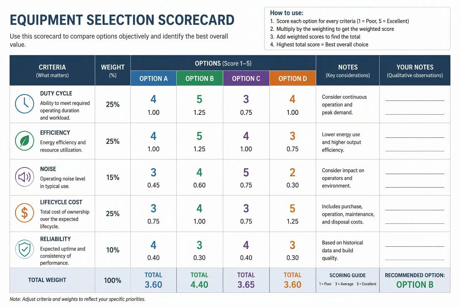
Fill the worksheet with measured or supplier-documented values, and flag every cell you haven’t verified yet. The example below compares a brushed gearmotor and a BLDC gearmotor for a continuous-duty pump drive rated at 8,000 hours.
Criterion | Weight | Brushed score | BLDC score | Evidence still needed |
|---|---|---|---|---|
Duty cycle and thermal margin | 25 | 3 | 4 | Winding temperature at 40 °C ambient |
Efficiency and energy | 15 | 2 | 5 | Input power at the duty point |
Noise and EMI | 15 | 3 | 4 | Emission scan with the production drive |
Service life and maintenance | 15 | 2 | 5 | Bearing and brush life data |
Lifecycle cost | 15 | 4 | 3 | Drive and harness cost at volume |
Supply and compliance risk | 15 | 4 | 3 | RoHS/REACH declarations and lead time |
Weighted total | 100 | 59 | 81 |
The brushed column isn’t beaten by the total; it’s beaten by its service-life score of 2 against an 8,000-hour requirement. Cut the duty cycle to intermittent use and that score rises, and the gap narrows sharply.
Sector Patterns and Use Cases
Sector patterns are starting points, not verdicts. They show you which gates usually bite first, so your prototype time goes at the right risk. In every case below, check the pattern against your own duty cycle, ambient and EMC limits before you commit.
Medical and lab devices
Medical and lab equipment usually pushes the noise, contamination and EMC gates to the front. Carbon brushes shed wear particles, so they’re a poor match for contamination-sensitive fluid handling. Precious-metal brushes cut arcing and particles but cost more and last less time (Allied Motion). Where the device falls under IEC 60601-1-2, the intended-use environment sets the immunity test levels, and the standard also sets emission requirements — so evaluate the motor and drive as part of the equipment, not on their own (IEC 60601-1-2). Allied Motion lists pumps, medical hand pieces and high-speed surgical handtools among BLDC examples, but a brushed unit still works for intermittent, low-duty mechanisms where you’ve designed in service access.
Industrial automation
Industrial automation usually binds on duty cycle, controllability and lifecycle cost. Continuous or near-continuous running makes brush wear the limiting factor: 2,000 to 5,000 runtime hours is typical for brushes, while brushless units usually pass 10,000 hours and are then limited by bearings and environment (Haydon Kerk Pittman). Where precise speed and torque control across the range matters, BLDC is usually the better fit, and its fit with IIoT monitoring supports predictive maintenance (Dunkermotoren). Simple conveyors and low-cost mechanisms still justify brushed gearmotors.
Security and consumer devices
Security and consumer devices usually bind on cost, size, acoustic noise and standby behaviour. Smart locks, access gates and small actuators often run short, infrequent duty cycles, which favours brushed gearmotors on upfront cost and simple voltage-based speed control. Battery-powered products tip the balance toward BLDC, because higher efficiency turns straight into runtime and battery life (Dunkermotoren). If the product sits in a quiet room, remember that commutation sparking is itself a noise source, so score acoustic and electrical noise together rather than separately (Mabuchi Motor).
Supplier and Compliance Readiness
A motor that wins the scorecard but arrives without documentation is a schedule risk, not a design win. Treat supplier readiness as a gate of its own: the evidence has to exist before you freeze the design, and it must cover the exact variant you’ll buy, not the whole family. For equipment placed on the EU market, RoHS restricts ten substances including lead and cadmium, and EMC compliance is required when the apparatus is placed on the market or put into service (RoHS Directive; EMC Directive). Ask for the declaration against your part number, not the catalogue page.
Documentation and QA evidence
Request a documentation pack that lets you verify rather than trust: the spec sheet for your exact part number, motor characteristic curves, dimensional drawings, RoHS and REACH declarations, and the inspection regime used at final test. Ask what outgoing inspection actually checks, at what sampling rate, and whether the supplier can share defect-rate data. For life-critical or high-duty applications, ask for the test conditions behind any quoted life figure, because brush life depends on load, voltage and environment and doesn’t transfer between applications (Haydon Kerk Pittman). INEED Motors supports this stage directly: inquiries are usually answered within 8 hours, customization covers shafts, windings, gear ratios, connectors and encoders, and products ship with RoHS and REACH documentation.
Controller and firmware ownership
BLDC selection doesn’t stop at the motor. The commutation controller, its power stage and its firmware become part of your product, and someone has to own them through the lifecycle. Decide early whether you buy an integrated motor-and-drive unit, use a separate third-party drive, or develop the drive in-house — each choice shifts cost, thermal derating and failure points. Integrated electronics simplify cabling but expose the electronics to motor heat, which can force derating compared with a separate motor and drive (Allied Motion). Agree with the supplier on who owns firmware updates, parameter tuning and fault diagnosis, and put it in writing before tooling.
Conclusion
Run the gates first, then score the trade-offs that remain. Safety, thermal margin, duty cycle, power source, noise and serviceability are pass-or-fail questions. A candidate that fails one doesn’t become acceptable because it wins on price or efficiency. Only the survivors deserve a weighted score, and only a score built on measured or documented values tells you anything.
Then prototype the worst case, not the nominal one. Run the candidate at maximum ambient, maximum continuous load and the longest single duty cycle your product allows, and test it with your own drive and firmware rather than the supplier’s bench setup. Speed-control accuracy is a useful check here: a good brushed motor holds speed to within about 10%, a good brushless motor is closer to 5%, and top-tier BLDC with a high-performance drive can reach 1% to 2% (Allied Motion). If your prototype misses that band, the problem may be tuning rather than the motor.
Finally, reassess lifecycle cost and supply risk before you release. Brush replacement isn’t a like-for-like swap: the commutator surface wears too, and some manufacturers use inaccessible brush designs to avoid warranty claims from poor servicing — so check the documentation and warranty before you assume field service is an option (Allied Motion). Weigh that against drive cost, lead time and second-source availability. The right answer is the one your evidence supports for this application, and it’s worth revisiting whenever duty cycle, volume or compliance scope changes.
FAQ
Which is better for a battery-powered device, brushed or brushless? Brushless, in most cases. A BLDC motor removes brush friction and voltage drop, so more of the stored energy reaches the shaft. That extra efficiency becomes runtime and battery life. The trade-off is the drive: you need a controller, and it draws its own small share of power. If the device runs for seconds a day, a brushed motor’s lower standby draw and simpler circuit can still win.
Can I run a brushless DC motor without a driver? No. A BLDC motor won’t spin from a bare DC supply, because something has to switch the phases in the right sequence as the rotor turns. You need either a separate drive or an integrated motor-and-controller unit. Budget for the drive’s space, cost and heat from the start; adding it later usually means redesigning the enclosure.
How long do brushed motors actually last? Expect roughly 2,000–5,000 hours on carbon brushes and around 1,000 hours on precious-metal types, depending on load, voltage and environment. Brushless units usually pass 10,000 hours and are then limited by their bearings. Multiply your required operating hours by the duty cycle to get shaft lifetime hours, then compare — a continuous-duty machine can wear out a brush set several times over within one service life.
Do brushed motors fail EMC testing? Not automatically, but they make it harder. Sparking at the brush-commutator interface produces both conducted noise along the cables and radiated noise, and that eats into your margin. Suppression components help, and many products pass. If the design has little room for filters or the limit is tight — medical equipment under IEC 60601-1-2, for instance — plan a pre-compliance scan early rather than discovering the problem at certification.
When does it still make sense to choose brushed? Four situations come up again and again: short or intermittent duty cycles, a tight upfront budget, very simple voltage-based speed control, and service access that lets someone replace brushes on a planned schedule. Smart locks, simple conveyors and low-cost actuators fit this profile well. Brushed also wins where the enclosure has no room for a drive.
What should I send a supplier to get a motor recommendation? Give them the output torque and speed you need at the shaft, the supply voltage and available current, the space envelope, the duty cycle and expected life, the ambient temperature, and any noise or EMC limits. Add the mounting and shaft interface, connector preference, and whether you need an encoder. With those in hand, a supplier can propose a motor and gearbox combination instead of guessing.
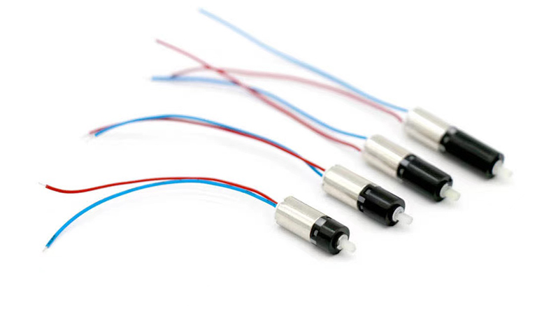
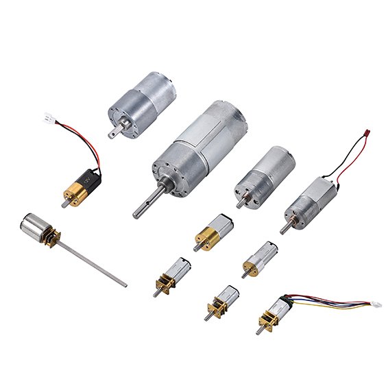
Does motor size limit which architecture I can use? Yes, and it’s worth checking early. Micro motors in the 6 mm to 42 mm diameter range are available in both brushed and brushless versions, but the drive takes space that a brushed motor doesn’t need, so a BLDC in the smallest frames can force a larger overall package once the controller is counted. Confirm the full assembly envelope, not just the motor body.