Picking a 12V worm gear motor really comes down to two questions. How much torque does your load need? And will the gearbox keep its position once you cut the power?
Get those wrong and you pay for it twice. The motor stalls under load, or a lifted weight slides back down the moment you switch the drive off.
This guide walks you through the checks you can run on any datasheet. Work out the load torque, read the rated and stall torque at the conditions they were measured under, match the gear ratio to your speed target, and then check the holding claim from the geometry instead of the marketing copy. That last step matters because a worm gear only self-locks when its lead angle is smaller than the friction angle between the worm and the wheel. You can test that against the numbers a supplier gives you.
The whole sequence needs a datasheet that lists rated and stall torque separately, each with its measurement condition. If a sheet leaves those out, you will know exactly what to ask for before you buy a sample.
This guide comes from INEED Motors, a maker of high-precision small gear motors, BLDC motors and miniature DC motors with more than a decade in the field. The range includes worm gear motors from 6mm to 42mm, and the company customises parameters like gear ratio, stall torque and rated voltage — the same parameters this guide is built around.
Prerequisites: What You Need Before You Start 12V Worm Gear Motor Selection

Before you run any calculation, you need five things in hand. Skip them and your numbers will look precise while meaning nothing.
Here’s what to gather:
Load torque, plus how it was measured. A number in kg·cm or N·m only helps if you know whether it was taken at the shaft, at the load, through a linkage, and at what temperature.
Duty cycle. Continuous, intermittent, or short bursts. The one firm continuous-duty rule here is to stay at 70–80% of rated torque, which is a very different target from a brief peak.
Ambient temperature. Precision Microdrives’ AB-032 application note makes the point that datasheet figures are taken at a stated voltage, so the same motor behaves differently under load — and that temperature changes both gearbox efficiency and how well the lubricant works.
Mounting orientation. Horizontal, vertical, or suspended. This decides whether holding even matters.
A datasheet that splits no-load, rated and stall figures instead of giving one torque number. INEED’s 12V worm gear motor N30 page shows the right shape: the IND-12GMWN30 covers 59:1 to 1168:1, with the 300:1 version rated at 6V (on-load torque 20 g·cm, stall torque 3600 g·cm, on-load speed 45 rpm) and the 1168:1 version rated at 12V (on-load torque 8 g·cm, stall torque 16800 g·cm, on-load speed 15 rpm), plus current at each point. What it does not give on its own is a numeric holding torque or a test condition for the self-locking claim — which is exactly why you still ask.
You should be comfortable reading a speed-torque curve. This is intermediate work, and it takes about 45 minutes.
A missing measurement condition is a finding, not a footnote. Ask the supplier for it.
Step 1: Calculate the Torque Your Load Actually Requires
Start with your load, not the datasheet. Figure out the torque your mechanism needs at the output shaft, then size for 1.5 to 2 times that number. Why the cushion? Efficiency varies, loads are uncertain, tolerances stack up, and startup transients spike the real demand above the ideal figure (Firgelli Automations DC gear motor guide, 2023-08-07). For continuous duty, stay at no more than 70 to 80 percent of the motor’s rated torque.
A lifted weight makes the math easy to see. Take a 2 kg mass on a 20 mm radius drum. The static load torque is 2 × 9.81 × 0.02 ≈ 0.39 N·m. Now add friction in the screw and bearings, the startup spike as the load accelerates from rest, and a wear allowance for the life of the unit. Each one is a separate line, and the sum is your calculated torque. Multiply that sum by your chosen factor to get the torque you actually need.
As a sanity check, Gian Transmission’s gearbox selection guidance suggests a 10 to 30 percent margin and a service factor of at least 1.25.
Key Takeaway: A continuous-duty torque figure and a momentary peak are two different numbers. Size the motor on the continuous figure, then confirm the peak on its own.
Verify your result: your required torque beats the calculated load torque by the factor you picked, and you have written that factor down along with the reason for it.
Step 2: Read Rated Torque and Stall Torque at Their Stated Condition
Most 12V worm gear motor datasheets show two torque numbers, and they answer different questions. Rated torque is the continuous, heat-limited figure, not the peak: it is the load the motor can carry all day without blowing past its insulation class limit, usually 130 °C Class B. Stall torque is the zero-speed maximum, the point where back-EMF drops to zero and stall current equals supply voltage divided by armature resistance. Never run the motor at stall — sustained stall current will almost certainly kill it early.
That difference shapes how you read the rest of the sheet. A torque figure only means something when you know the condition it was measured under. Datasheet numbers are taken at a stated voltage, and temperature shifts both gearbox efficiency and how well the lubricant works, so a 12V rating tells you nothing about 9V or 60 °C. Holding torque is also not a standard rating, so confirm it with the supplier instead of assuming a separate heat limit exists.
Verification checkpoint: both figures are written down next to the voltage, duty cycle and ambient temperature they were measured at. If the sheet does not say, ask before you compare suppliers.
Step 3: Match Gear Ratio to the Required Speed and Torque
Gear ratio decides two things at once: the output speed and torque you get, and the worm start count that decides whether the gearbox holds. Treat 12V worm gear motor gear ratio as a two-column choice, not a single number.
Speed and torque side | Starts and lead angle side |
|---|---|
Higher ratio: lower output speed, higher available torque | Single-start worm, lead angle λ ≈ 2°–6°, ratio i = 20–100: reliably self-locking |
Lower ratio: higher output speed, less torque multiplication | Double-start, λ ≈ 6°–12°, i = 10–20: marginal holding |
Ratio chosen to meet the speed target at rated voltage | Multi-start, λ > 12°, i = 5–10: does not self-lock |
Here’s the trap: a ratio can hit your torque target and still fail the holding test, because holding depends on worm starts, not ratio alone. Single-start worms at 20:1 or higher are the designs that reliably self-lock (wumadrive WMRV self-locking guide, retrieved 2026-06-29).
Efficiency runs the other way. Manufacturer test data show it drops as reduction ratio climbs, with ratios of 20:1 or less reaching 90%+ after run-in — and run-in usually takes 10 to 100 hours. The catch is that a more efficient reducer is also more likely to back-drive (Winsmith worm gear reducer efficiency data, 2025-09-15).
Check before moving on: the ratio meets your speed target at the stated supply voltage, and you know its worm start count.
Step 4: Verify Self-Locking from Lead Angle and Friction Angle
Worm gear motor self-locking is something you can check, not a label you just trust. The worm only holds when its lead angle λ is smaller than the friction angle ρ, where ρ = arctan(μ) (507 Ways to Move Part 7, retrieved 2026-04-01). At λ = ρ, back-driving efficiency is exactly zero.
Think of it as a slope. If the slope is gentle enough and the surface rough enough, the load cannot push itself back down. In practice, that only works below a lead angle of roughly 5°. Between 5° and 10° the property turns unreliable, and above 10° to 15° it is gone (507 Ways to Move Part 7, retrieved 2026-04-01).
The friction angle has to be larger than the worm’s lead angle, and it is not a fixed number. For steel on bronze with oil lubrication, μ runs from about 0.03 to 0.10, which puts ρ between roughly 1.7° and 5.7°. Motion Control Tips cites a static μ near 0.15 for a steel worm and bronze gear, pushing ρ to 8° to 9°.
Run the numbers on your own unit. With a typical μ of 0.12, a 5° lead angle gives about 41% efficiency and still self-locks, because ρ = 6.84° beats λ (Firgelli Automations self-locking calculator, retrieved 2026-04-01).
Checkpoint: you have compared your lead angle against a range of friction angles, not one assumed value.
Step 5: Stress-Test the Holding Claim and Decide on a Brake
Back-driving is the failure mode that turns a static self-locking claim into a safety question. A 5° lead angle self-locks at a friction coefficient of 0.13 (friction angle 7.4°). But let shock or vibration drop that coefficient to 0.08 and the friction angle falls to 4.6°, and the worm back-drives. Once it starts, it usually keeps going, because friction falls further as speed rises (Machine Design, “Self-locking worm gears: fact or fiction?”, 2000). The property only holds while the gears sit still — every theoretical analysis of self-locking worm gears covers static conditions only, and temperature shifts friction too. Above 80 °C the oil film weakens and you get close to the critical threshold.
So here is the rule. For vertical lifting, suspended loads, or any safety-critical holding job, never lean on self-locking alone. A gear that is self-locking on paper can still creep under vibration, so it needs an independent mechanical brake (Wasil Zafar, “Worm Gears”, 2026). Checkpoint: you have either specced a mechanical brake or written down why the application is not safety-critical.
Common Mistakes in 12V Worm Gear Motor Selection
Trusting a self-locking claim with no numbers behind it. One supplier sheet says self-locking but never gives the holding torque or how it was measured, so you cannot check the claim against your load. Ask for the lead angle, the friction angle, and the test condition before you treat it as a holding force.
Reading stall torque as an operating point. Stall torque marks the limit you must not cross, not a torque you can run at all day. Size the load against rated torque and keep the duty cycle inside the rating.
Comparing torque figures taken at different voltages or duty cycles. A figure quoted at 12V continuous is not the same animal as one quoted at 24V intermittent. Put both on the same voltage and duty before you compare.
Treating holding torque as a standard rating. It is not standard, so two suppliers can quote the same motor differently. Ask each one how they measured it.
Assuming a high ratio guarantees holding. Single-start worms at 20:1 or higher are the designs that reliably self-lock. A high ratio on its own proves nothing. Check the lead angle, not the ratio.
What Success Looks Like and What to Do Next
Your 12V worm gear motor selection is done when five things are written down, not just remembered: a required torque figure with its margin, rated and stall torque each recorded with the condition they were measured under, a gear ratio whose worm start count you know, a lead angle checked against a range of friction angles, and a brake decision you can defend.
Be honest about the fit. Worm gears are a poor choice where high efficiency or frequent reversing is required, so if either dominates your duty cycle, rethink the architecture before you order samples. INEED’s range runs from 6mm to 42mm, so you can match frame size to the space you have.
The one question to put to any supplier: what voltage, duty cycle and ambient temperature were these torque figures measured at?
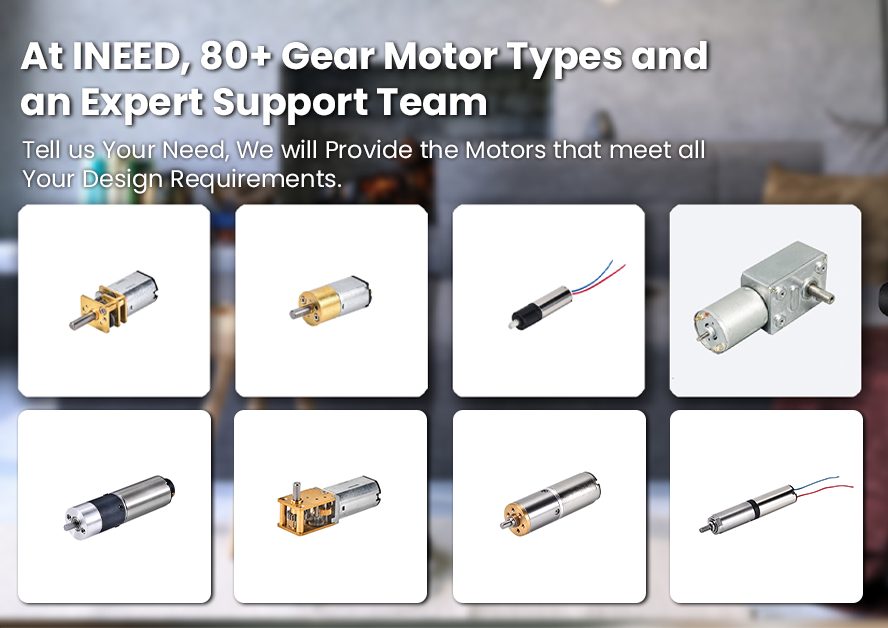
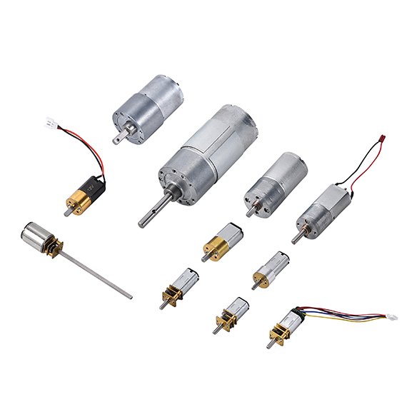
INEED’s own line-up shows how much the answer moves with ratio. The N30 12V worm gear motor spans 59:1 to 1168:1, where stall torque climbs from 3600 to 16800 g·cm as on-load speed drops from 45 to 15 rpm. The bigger 24 mm 370 worm drive motor reaches 1/46 to 1/2000, with stall torque from 1000 to 5000 g·cm across the 54:1 to 500:1 builds. The N20 micro worm gear motor and the compact 12mm coreless small worm gear motor cover the smaller end. Each is quoted on-load, not at one headline number — which is the whole reason you ask for the full test condition.
From there, request a spec review, a sample, or a chat with an engineer.
FAQs
How long does 12V worm gear motor selection take?
The math is an afternoon. Gathering the data is what stretches it out. If the datasheet states rated and stall torque at a defined voltage and temperature, Steps 1 to 4 wrap up in a few hours. If it does not, budget a week of back-and-forth with the supplier before you can verify anything.
Does a higher ratio always mean more holding?
No. Holding comes from geometry, not ratio alone. For self-locking to hold, the friction angle between worm and wheel has to be larger than the worm’s lead angle. A high ratio usually brings a small lead angle, which helps — but ratio is only a hint at the geometry, not the geometry itself.
What if the supplier cannot state a lead angle?
Ask for the lead angle and the friction coefficient in writing. If neither shows up, treat the self-locking claim as unverified and plan for a brake. You can estimate the margin from measured back-driving torque, but that is a bench test, not a datasheet number.
Can self-locking replace a brake on a vertical load?
No. Self-locking holds a static load, but every theoretical analysis of it covers static conditions only, and vibration or thermal cycling can let the load creep even when the geometry says it should hold. On a suspended load, never rely on self-locking alone for safety-critical holding. Fit an independent mechanical brake.
How does ambient temperature change the holding margin?
Temperature shifts the friction angle, and with it your margin. The worm starts decide whether the gear can back-drive at all, and above 80 °C the oil film weakens and you edge toward the critical threshold. A motor that holds at 25 °C may not hold at 80 °C, so verify the claim at the temperature you actually run at.
Conclusion
Good 12V worm gear motor selection comes down to two calls: the torque your load really needs, with margin, and whether holding is a verified condition rather than an accepted claim.
The checklist is short:
Calculate the load torque at the worst-case operating point, then add margin for friction, voltage sag and temperature.
Read rated and stall torque at the condition they were measured under, and ask for voltage, duty cycle and ambient temperature when the sheet leaves them out.
Match the gear ratio to the speed and torque you need, checking both against the same operating point.
Verify self-locking using lead angle against friction angle, then stress-test the holding claim on a vertical or suspended load before you decide on a brake.
Self-locking holds a load while the motor sits still. It is not a brake, and treating it as one is the mistake that costs the most.
Once those two calls are settled, put the numbers in front of a supplier and ask them to confirm the figures at your duty cycle, not theirs.